Method and equipment for detecting stress resistance of display screen

A display screen and anti-stress technology, applied in nonlinear optics, instruments, optics, etc., can solve problems such as cost loss and uneven screen display

Active Publication Date: 2014-05-21
TRULY OPTO ELECTRONICS
View PDF6 Cites 7 Cited by
  • Summary
  • Abstract
  • Description
  • Claims
  • Application Information

AI Technical Summary

Problems solved by technology

Since the display screen has been fully bonded to the touch screen during the test, and the chip and circuit board have been bound, if the test finds that there is a problem of uneven display, the entire touch display module will be scrapped, and the general price will be 200 more than 100 yuan, resulting in a huge loss in cost

Method used


Image

  • Method and equipment for detecting stress resistance of display screen

Examples


Embodiment 1

[0028] This embodiment provides a method for testing the stress resistance capability of a display screen, the method comprising the following steps:

[0029] Step S1: Keep the display screen to be tested in an undriven state, and perform vacuum adsorption on the surface of the display screen for a preset time.

[0030] During the vacuum adsorption process of the display screen, the adsorption point on the display screen is continuously subjected to stress, which will cause the cell thickness of the liquid crystal cell at this position to be gradually greater than that of the non-absorbed area.

[0031] In this embodiment, the display screen to be detected may be a display screen with a polarizer attached, or a display screen without a polarizer attached.

[0032] The duration of vacuum adsorption on the display screen (that is, the preset time) is not limited, and the preset time can preferably be determined according to actual quality requirements for the display screen. Si...

Embodiment 2

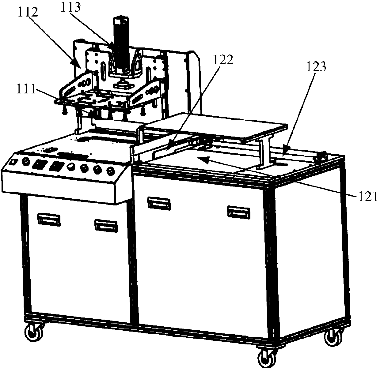
[0046] Corresponding to the above method embodiments, this embodiment provides a device for testing the stress resistance capability of the display screen, the structure of the device is as follows figure 1 As shown, it includes: a vacuum nozzle 111 , a first guide rail 112 and a first cylinder 113 .

[0047] In order to further improve the functions of the above-mentioned equipment, the above-mentioned equipment may further include: a backlight 121; in order to further improve the degree of mechanical automation of the above-mentioned equipment, the above-mentioned equipment may further include: a second guide rail 122 and a second cylinder 123.

[0048] The device for testing the stress resistance capability of the display screen provided in this embodiment can be divided into two parts: a vacuum adsorption area and an adjacent observation area. The vacuum suction area is used to carry out vacuum suction operation on the display screen, including: vacuum suction nozzle 111, ...


PUM

PropertyMeasurementUnit
diameteraaaaaaaaaa

Abstract

The invention provides a method and equipment for detecting the stress resistance of a display screen. The method comprises the following steps: enabling the display screen to be detected to be in an undriven state and carrying out vacuum adsorption on the surface of the display screen for preset time; carrying out statistics on time that color spots disappear on the display screen after vacuum adsorption is finished; and comparing the time that the color spots disappear with a threshold value of the time that the color spots disappear, if the time that the color spots disappear is less than or equal to the threshold value, judging the stress resistance of the display screen is qualified, or judging the stress resistance of the display screen is unqualified. By the method provided by the invention, the display screen of which the stress resistance accords with the requirement can be screened in advance; the higher the stress resistance of the display screen is, the difficult the problem of nonuniform image display of a touch control display module, which is caused by variation of the thickness of a box due to nonuniform partial stress, is to generate in the process of subsequently attaching to a touch screen, and thus, the method provided by the embodiment reduces the probability of generating the problem of nonuniform image display of the module and reduces waste of cost.

Description

technical field [0001] The invention relates to the technical field of display modules, and more specifically, to a method and equipment for testing the stress resistance capability of a display screen. Background technique [0002] The touch display module mainly includes two parts: the display screen and the touch screen. There are usually two ways to combine the display screen and the touch screen: frame-mounted and full-mounted. Among them, the full lamination uses water glue or optical glue to completely paste the display screen and the touch screen together in a seamless manner. The full lamination technology cancels the air between the screens and helps reduce the reflection between the display screen and the touch screen. , which can make the module look more transparent and enhance the display effect of the module. [0003] During the full lamination process of the display screen and the touch screen, if the force on the display screen is uneven, the thickness of t...

Claims


Application Information

Patent Timeline
Patent Type & Authority Applications(China)
IPC IPC(8): G02F1/13
Inventor 黄泽魁林金鸿施远彬张翔李建华
Owner TRULY OPTO ELECTRONICS
Why Eureka
Try Eureka