Eureka AIR delivers breakthrough ideas for toughest innovation challenges, trusted by R&D personnel around the world.

Image display apparatus

a display apparatus and display panel technology, applied in the direction of supporting structure mounting, circuit arrangement on conductive chasis, instruments, etc., can solve the problems of increased deformation amount of display panel and display panel stress, and increased display panel unevenness, etc., to reduce display unevenness

Active Publication Date: 2014-08-21
CANON KK
View PDF25 Cites 10 Cited by
  • Summary
  • Abstract
  • Description
  • Claims
  • Application Information

AI Technical Summary

Benefits of technology

The patent invention aims to address the issue of display unevenness that can occur when a warp occurs or external force is applied to the display panel of an image display apparatus. The technology described in the invention can help to reduce this unevenness and create a more uniform display.

Problems solved by technology

However, the related art and the image display apparatus of Japanese Patent Application Laid-open No. 2010-204357 sometimes have not been able to cope with changes in use environment.
With this, a panel holding force is reduced, and the deformation amount of the display panel and the stress of the display panel are increased when an external force is applied to the surface of the liquid crystal panel so that the display unevenness is likely to occur.

Method used


Image

  • Image display apparatus
  • Image display apparatus
  • Image display apparatus

Examples


first embodiment

[0034]Hereinbelow, a first embodiment according to the present invention will be described with reference to the drawings.

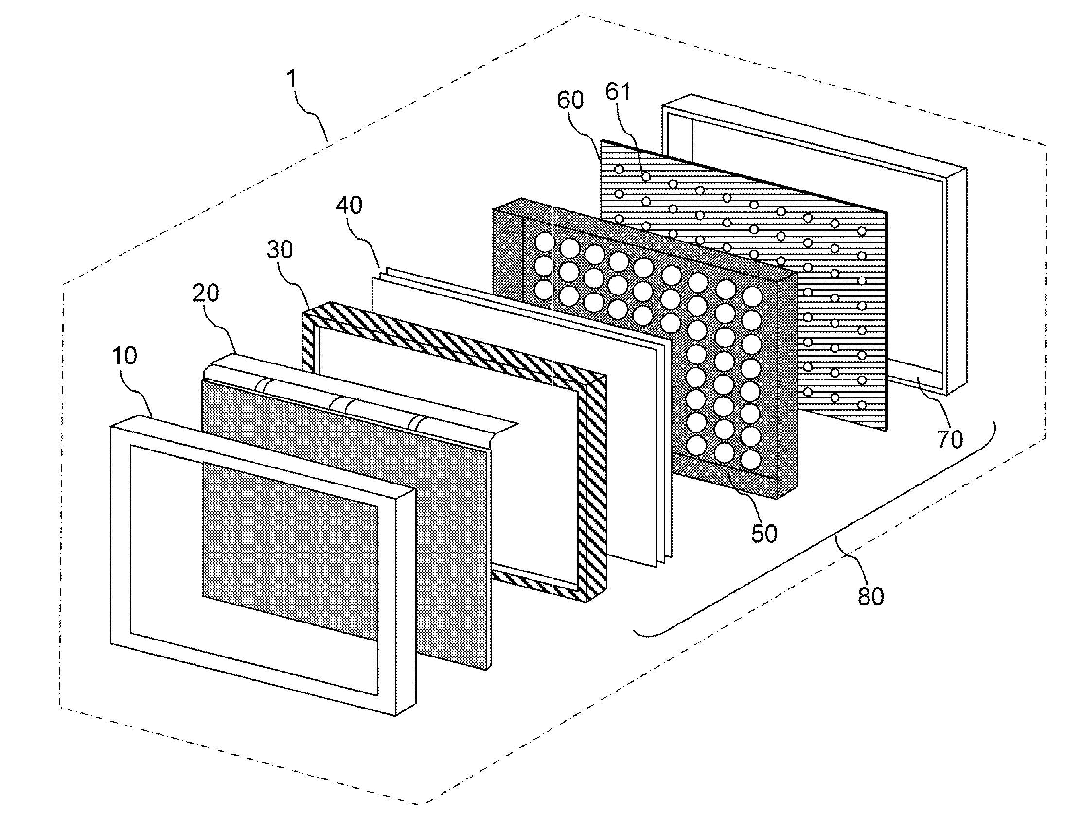
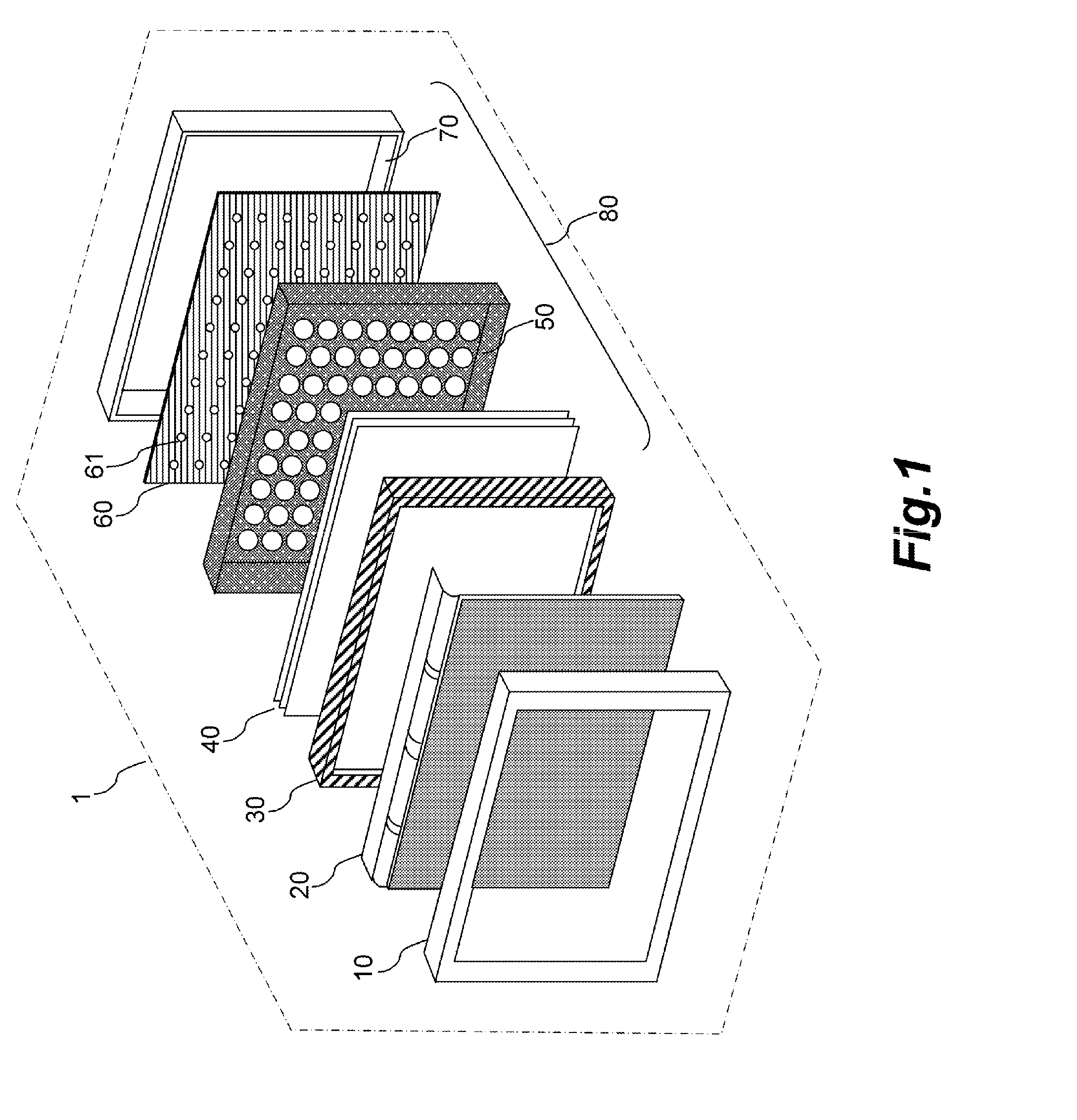
[0035]FIG. 1 is an exploded perspective view schematically showing the entire image display apparatus according to the first embodiment. An image display apparatus 1 includes a frame 10, a display panel 20, a panel holder 30, optical sheets 40, a reflection sheet 50, a substrate 60, and a case 70. The frame 10 is a holding member that holds four sides of the display panel 20, and metal is often used as the material of the frame 10. The frame 10 is formed by press working or machining, but may also be formed by resin molding. The panel holder 30 is preferably formed by resin molding, but may also be formed of a metal material. The panel holder 30 holds and accommodates the display panel 20 so as to maintain a specific space from the optical sheets 40.

[0036]The optical sheets 40 diffuse light from a backlight unit 80. The reflection sheet 50 reflects light of light...

second embodiment

[0052]Next, a second embodiment of the present invention will be described with reference to the drawings. In the second embodiment, the configuration different from that of the first embodiment will be described in detail.

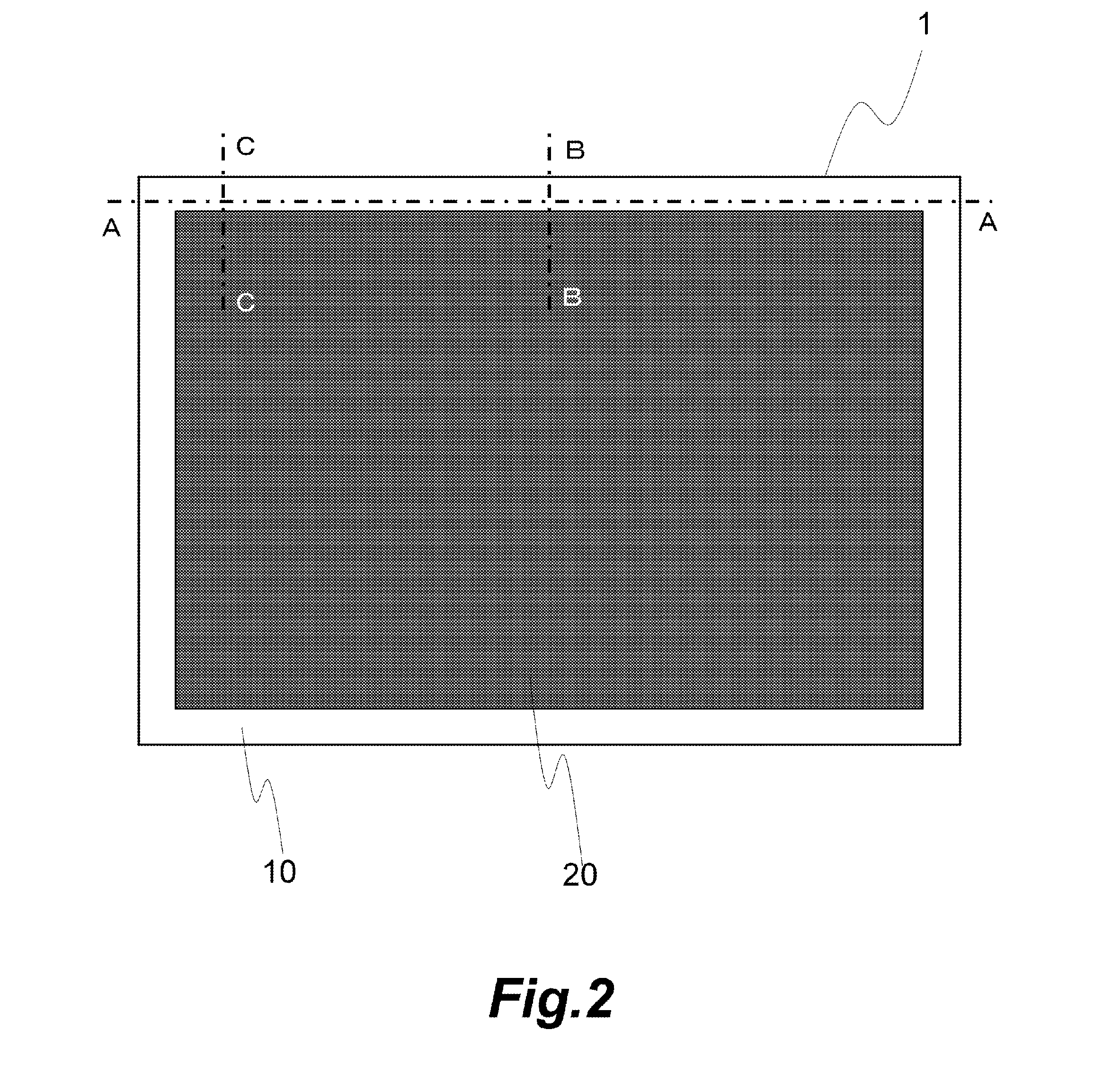
[0053]FIG. 8 is a cross-sectional view similar to the A-A cross section of FIG. 2 schematically showing an upper side of an image display apparatus according to the second embodiment.

[0054]As shown in FIG. 8, a drawn portion 211 is provided at the center in the longitudinal direction of a frame 210. Similarly to the first embodiment, metal is often used as the material of the frame 210, and the frame 210 is formed by press working or machining. However, the frame 210 may also be formed by resin molding. The thickness of a front elastic body 201 is uniform, and the material of the front elastic body 201 is the same as that in the first embodiment. However, the pressing force to the display panel 20 in the central portion provided with the drawn portion 211 is large...

third embodiment

[0058]Next, a third embodiment of the present invention will be described with reference to the drawings. In the third embodiment, the configuration different from that of the first embodiment will be described in detail.

[0059]FIG. 9 is a cross-sectional view similar to the A-A cross section of FIG. 2 schematically showing an upper side of an image display apparatus according to the third embodiment.

[0060]As shown in FIG. 9, at least one half-pierced portion 311 as a protruded portion protruded toward the display panel 20 is provided in a portion in the vicinity of the center in the longitudinal direction of a frame 310. The position of the half-pierced portion 311 and the number thereof can be determined according to the specifications of the display panel 20 and the frame 310. The frame 310 is formed by press working or machining by using metal as the material. The frame 310 may also be formed into a shape similar to the half-pierced portion 311 by resin molding, and the half-pier...


PUM


Abstract

The image display apparatus includes a display panel, a holding member that holds four sides of the display panel, and a cushioning member that is disposed between the display panel and the holding member and exerts pressing force corresponding to deformation amount on the display panel. In a state where the warp present in the display panel is smaller than the warp in its maximum warp state, the pressing force exerted on the display panel from the cushioning member in a region at each of both end portions of at least one of the four sides of the display panel is smaller than the pressing force exerted on the display panel from the cushioning member in a region at a central portion of the side.

Description

BACKGROUND OF THE INVENTION[0001]1. Field of the Invention[0002]The present invention relates to an image display apparatus.[0003]2. Description of the Related Art[0004]In liquid crystal and organic electroluminescence (EL) display panels, display elements such as liquid crystal and organic light-emitting elements are provided between two glass substrates formed with thin film devices.[0005]A conventional structure will be described with reference to FIGS. 15 and 16. An image display apparatus 1 having a display panel 20 is configured such that a metal case 70 in which the display panel 20 is accommodated or bonded and a base 75 are disposed on the opposite side of a display surface, and the side of the display surface is covered with a metal frame 10. The display panel 20 is a liquid crystal display panel. The image display apparatus 1 includes the display panel 20, a backlight unit for illuminating the display panel 20, and optical sheets for condensing light from the backlight un...

Claims


Application Information

Patent Timeline
Patent Type & Authority Applications(United States)
IPC IPC(8): H05K7/14
CPCH05K7/1417G02F1/133308G02F2201/54
Inventor OHTOMO, RYO
Owner CANON KK
Why Eureka
Eureka Blog
Learn More