Display device and scanning line driving device

a technology of a display device and a scanning line, which is applied in the field of display devices, can solve the problems of difficult to narrow the frame of the liquid crystal panel, and large area other than that of the display pixels, so as to reduce the impedance of wires, reduce the unevenness of display luminance, and reduce the effect of wire impedan

Inactive Publication Date: 2011-03-03
SHARP KK
View PDF17 Cites 10 Cited by
  • Summary
  • Abstract
  • Description
  • Claims
  • Application Information

AI Technical Summary

Benefits of technology

[0043]In the technique disclosed in Patent Literature 1, it is necessary to reduce impedance of wires that supply the storage capacitor driving signals to the storage capacitors, in order to reduce the unevenness in display luminance in the liquid crystal display panel. Further, as a method for reducing the impedance of wires, thickening line width of the wires may be considered.

Problems solved by technology

This causes the liquid crystal display panel to have an extremely thick core wiring, thereby causing an area other than that of display pixels to be large in area.
As a result, it is difficult to narrow a frame of the liquid crystal panel.
As a result, the liquid crystal display panel requires many voltage sources for generating the CS voltage, and together with this, the area other than that of the display pixels become large.
As a result, also with the technique disclosed in Patent Literature 2, it is difficult to narrow the frame.

Method used


Image

  • Display device and scanning line driving device
  • Display device and scanning line driving device
  • Display device and scanning line driving device

Examples


embodiment 1

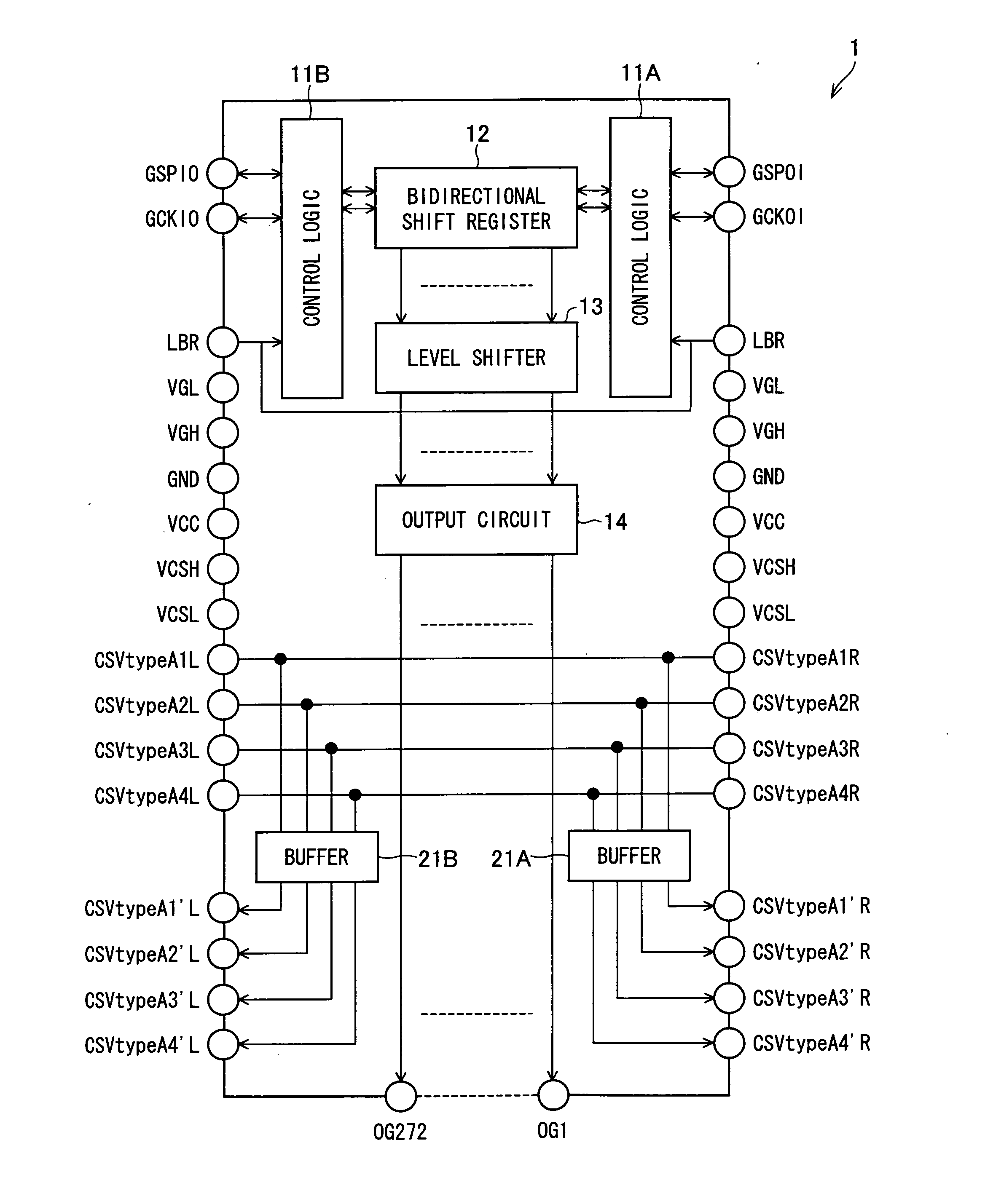
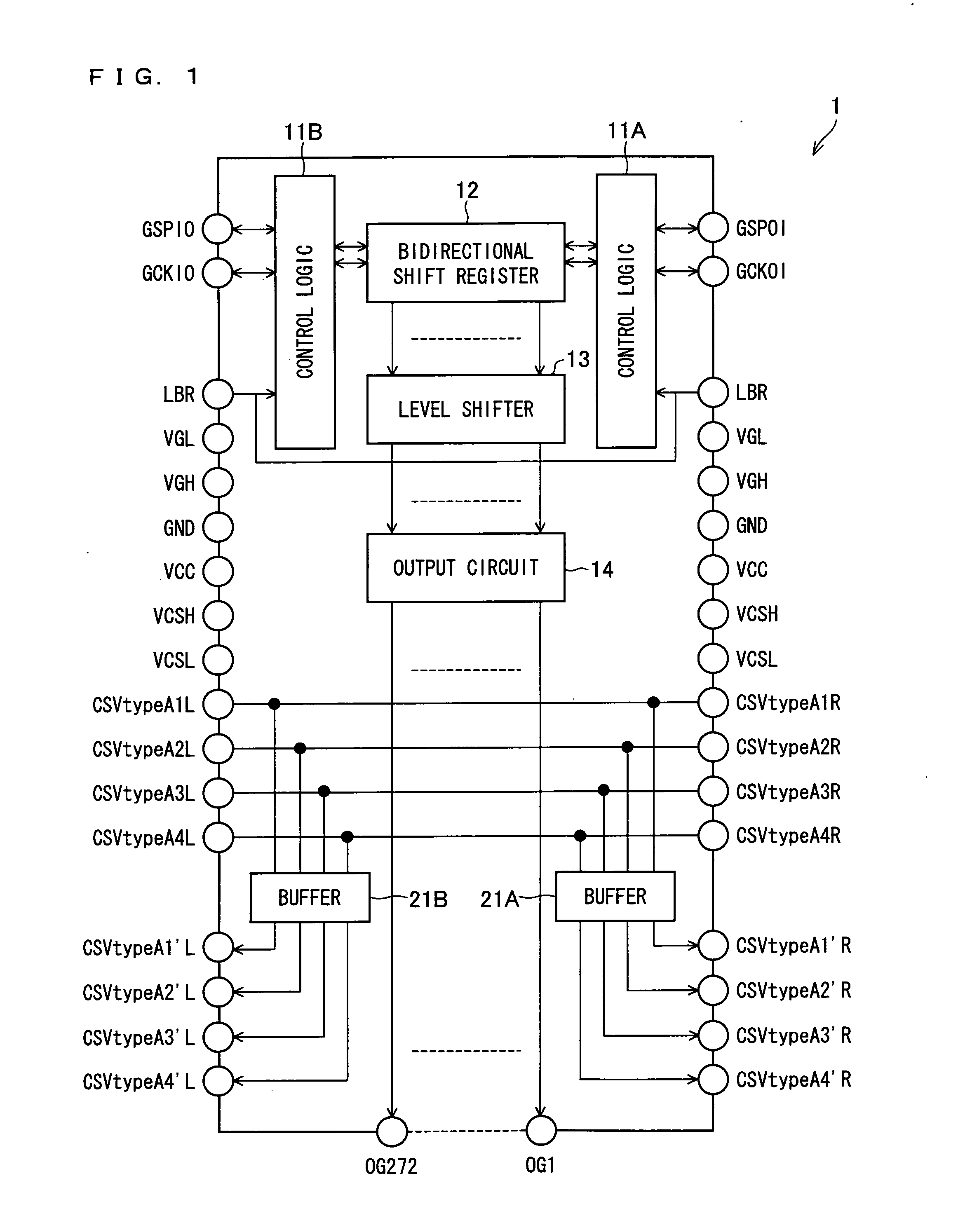
[0142]FIG. 1 illustrates one embodiment of the present invention, and is a block diagram schematically illustrating a configuration of a scanning line driving device.

[0143]A gate driver (scanning line driving device) 1 illustrated in FIG. 1 includes control logics 11A and 11B, a bidirectional shift register 12, a level shifter 13, and an output circuit 14. Furthermore, the gate driver 1 includes buffers 21A and 21B.

[0144]The round members that are illustrated in FIG. 1 are all terminals provided in the gate driver 1, and the signs (letters) that are given to the round members are terminal names of the terminals.

[0145]Terminals “LBR” provided in the gate driver 1 are input terminals in which control signals indicating a shifting direction of the bidirectional shift register 12 are inputted. The terminals “LBR” have a state “H” and a state “L”. The gate driver 1 controls a shifting direction of the bidirectional shift register 12 by causing the terminals “LBR” to switch between the st...

embodiment 2

[0247]FIG. 19 is a block diagram schematically illustrating a scanning line driving device provided in a display device according to the present embodiment.

[0248]A gate driver mounted substrate (scanning line driving device) 401 illustrated in FIG. 19 includes an interposer substrate (substrate) 403 on which a gate driver (integrated circuit) 402 is mounted.

[0249]The gate driver 402 includes control logics 11A and 11B, a bidirectional shift register 12, a level shifter 13, an output circuit 14, and a buffer 22, and has an identical configuration as the gate driver 2 illustrated in FIG. 5.

[0250]The following description explains functions of the terminals provided in the gate driver mounted substrate 401. Each of the terminals provided in the gate driver mounted substrate 401 are illustrated in FIG. 19 as round members. Moreover, signs (letters) provided to the round members denote the terminal names of the respective terminals provided in the gate driver mounted substrate 401. The t...


PUM


Abstract

In a display device driven by multi-picture element driving, in order to realize narrowing of a frame, a gate driver provided in the display device includes buffers. Storage capacitor driving signals are inputted in the buffers. In at least one embodiment, once the storage capacitor driving signals are inputted, the buffers shape waveforms of the storage capacitor driving signals, and outputs the storage capacitor driving signals thus shaped to storage capacitor wires via terminals “CSVtypeA1′R” to “CSVtypeA4′R” and terminals “CSVtypeA1′L” to “CSVtypeA4′L”. The buffers supply storage capacitor driving signals reduced in waveform rounding as such, to drive a storage capacitor that is connected to the storage capacitor wires.

Description

TECHNICAL FIELD[0001]The present invention relates to a display device or the like used in for example a word processor, personal computer, and receiver of a television broadcast. Particularly, the present invention relates to a display device of an active matrix liquid crystal display device or the like, and a scanning line driving device for driving scanning lines that are provided in the display device.BACKGROUND ART[0002]Liquid crystal display devices are flat display devices having excellent advantages such as high definition, thin thickness, lightweight, and low power consumption. Along with the improvement in displaying abilities, productivity and price competitiveness against other display devices, the liquid crystal display device market has been rapidly expanding in its scale.[0003]Under the progressing situation in improvement of display quality, problems regarding viewing angle characteristics have become newly revealed with the liquid crystal display devices, such as a ...

Claims


Application Information

Patent Timeline
Patent Type & Authority Applications(United States)
IPC IPC(8): G09G5/02
CPCG09G3/3655G09G3/3677G09G2300/0443G09G2300/0447G09G2320/028G09G2310/0289G09G2310/0291G09G2320/0223G09G2300/0876
Inventor KATSUTANI, MASAFUMIORISAKA, YUKIHISAWATANABE, TAKUYA
Owner SHARP KK
Why Eureka
Try Eureka