Fingerprint image capturing system

A fingerprint, top surface technology, applied in instruments, character and pattern recognition, computer parts and other directions, can solve the problems of fingerprint image blur, edge dark area, etc.

Active Publication Date: 2014-05-21
GINGY TECH
View PDF8 Cites 24 Cited by
  • Summary
  • Abstract
  • Description
  • Claims
  • Application Information

AI Technical Summary

Problems solved by technology

[0003] The purpose of the present invention is to provide a fingerprint imaging system, so as to solve the problem t

Method used


Image

  • Fingerprint image capturing system
  • Fingerprint image capturing system
  • Fingerprint image capturing system

Examples


Embodiment Construction

[0025] Below in conjunction with accompanying drawing, structural principle and working principle of the present invention are specifically described:

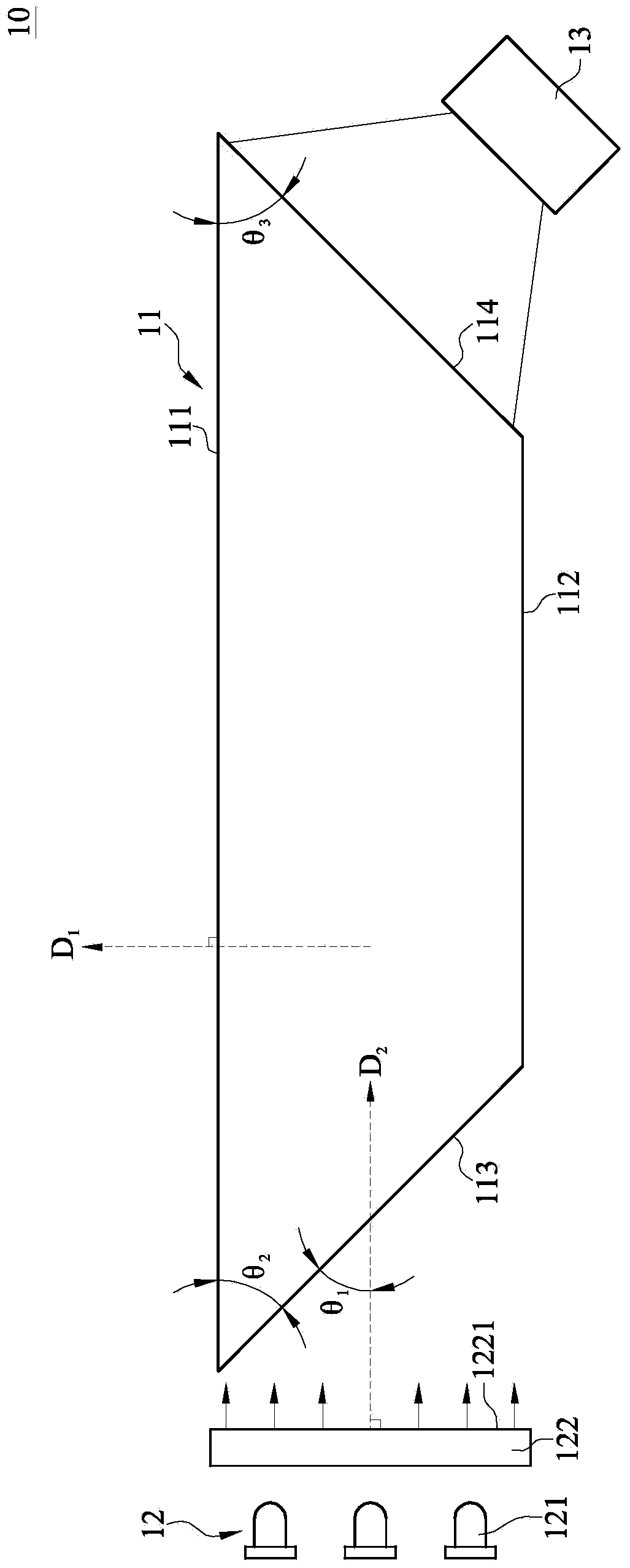
[0026] Please refer to figure 1 , figure 1 Shown is a schematic diagram of the fingerprint imaging system of the present invention.

[0027] The fingerprint imaging system 10 of the present invention includes an acupressure member 11 , a surface light source module 12 and an image capturing module 13 .

[0028] The acupressure member 11 is a transparent plate made of glass (model specification: BK7) or acrylic (Polymethylmethacrylate, PMMA). The refractive index n1 of the acupressure member 11 ranges from 1.49 to 1.52.

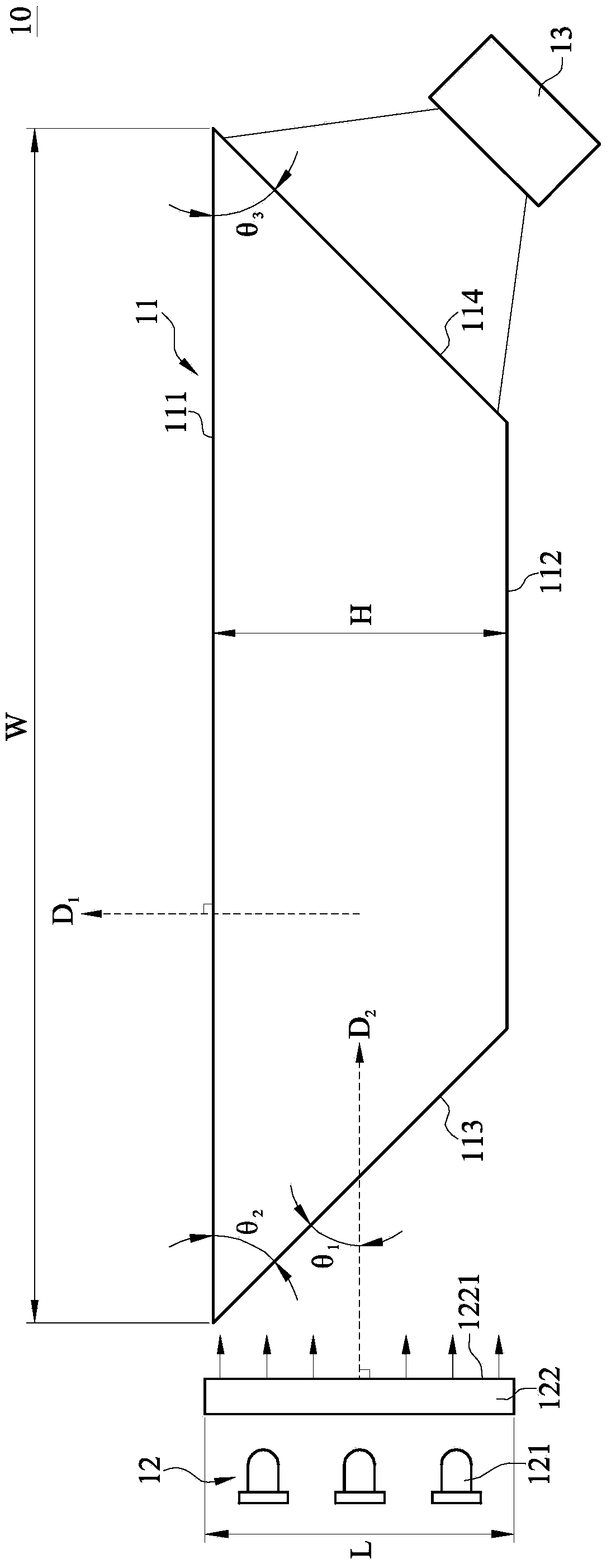
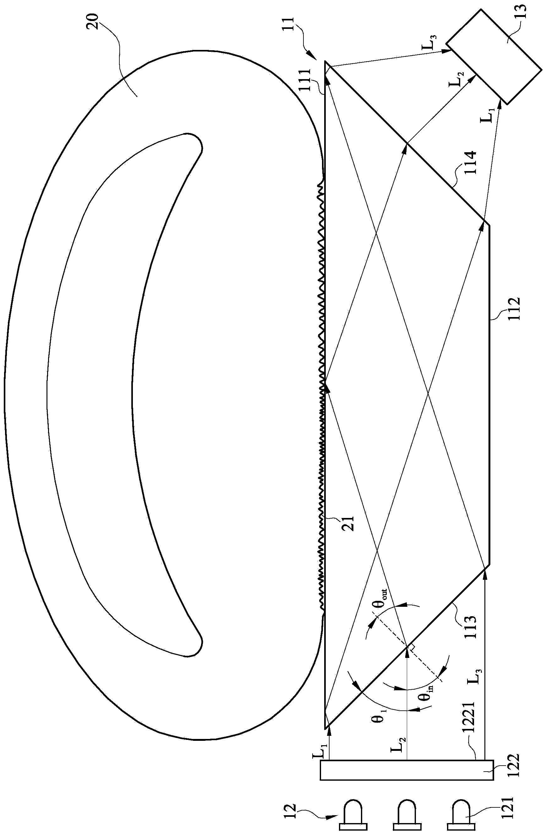
[0029] The cross section of the acupressure member 11 is a trapezoidal shape, which is composed of a top surface 111 , a bottom surface 112 , a light incident surface 113 and a light exit surface 114 . The top surface 111 of the acupressure member 11 is used for a finger to touch, and the width of the top s...


PUM


Abstract

A fingerprint image capturing system includes a fingerprint touch apparatus. The fingerprint touch apparatus includes a top surface, a bottom surface, a first normal line, a second normal line, a light input surface and a light output surface. The first normal line is perpendicular to the top surface. The light input surface and the light output surface are located on two opposite sides of the fingerprint touch apparatus. The light input surface corresponds to a planar light source module and the light output surface corresponds to an image capturing module. The planar light source module includes a light-emitting plane, and the light-emitting plane is parallel to the first normal line. The second normal line is perpendicular to the light-emitting plane. The second normal line and the light input surface form a first angle therebetween. The range of the first angle falls within 30 degrees to 45 degrees.

Description

technical field [0001] The invention relates to an imaging system, in particular to a fingerprint imaging system for capturing fingerprint images. Background technique [0002] Generally speaking, the usual method of reading fingerprints by fingerprint recognition devices is to read fingerprints by fixing fingers, for example, using a pressure plate for fingers to touch, and then using multiple light-emitting elements to provide a lens to capture fingerprint images of fingers touching the pressure plate In order to meet the principle of total reflection, the fingerprint identification device must have a specific angle between the lens, finger and light source, so as to pick up obvious and clear fingerprints, so that the existing optical type Fingerprint identification devices generally have the problems of large size and inability to be thinned, and there are disadvantages of dark areas at the edge of the captured fingerprint image. Contents of the invention [0003] The ...

Claims


Application Information

Patent Timeline
IPC IPC(8): G06K9/20G06K9/00
CPCG06V40/1324
Inventor 吴建兴
Owner GINGY TECH
Why Eureka
Try Eureka