Apparatus and method for adhering member
A technology for sticking devices and components, which is applied in the directions of electrical components, secondary processing of printed circuits, and manufacturing of printed circuits, can solve the problems of unstable accuracy, easy deterioration of components, and large energy loss, and achieves simple structure and reliable fixation. , the effect of high-precision processing
- Summary
- Abstract
- Description
- Claims
- Application Information
AI Technical Summary
Problems solved by technology
Method used
Image

Examples
no. 1 approach )
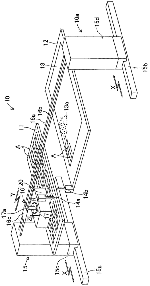
[0029] Hereinafter, a first embodiment of the present invention will be described with reference to the drawings. figure 1 The sticking device 10 of the components of this embodiment is shown. This part sticking device 10 is a fixed part for conveying the film-shaped small part A arranged on the upper surface of the bracket 11 and sticking it to the fixed part 13 composed of an electronic substrate provided on the upper surface of the fixing table 12. part 13a of the device. The small part A is made of thermoplastic polyimide, and when heated to about 200° C., it can be plasticized to produce adhesiveness, and is fixed to the fixed portion 13 a after being cured. In addition, as a material constituting the small part A, a thermoplastic resin material or a thermosetting resin material other than polyimide may be used.
[0030] In addition, the fixed member 13 is formed of a resin material such as polyimide. The component sticking device 10 includes a transport device 10a for...
no. 2 approach )
[0065] Figure 6 The heating and holding device 61 included in the component sticking device according to the second embodiment of the present invention is shown. In this heating and holding device 61 , the holding portion 65 does not hold the small piece component A or the small piece component B by suction, but is configured to hold the small piece component A or the small piece component B by gripping using a mechanical mechanism. As the holding portion 65, various structures can be used, for example, a frame-shaped structure capable of holding the small piece A or the small piece B by inserting the small piece A or the small piece B into the frame, or a structure having multiple A claw and can hold the structure of small piece A or small piece B by pinching small piece A or small piece B with the claw. The structure of other parts of this heating and holding device 61 is the same as that of the above-mentioned heating and holding device 41 . Therefore, the same reference...
no. 3 approach )
[0071] Figure 8 The heating and holding device 81 included in the component sticking device according to the third embodiment of the present invention is shown. In this heating and holding device 81 , a holding portion 85 is configured such that a solenoid 85 b for generating magnetism is housed in a box-shaped housing portion 85 a made of a steel plate. Moreover, the wiring 85c connected to the solenoid 85b extends outside from the upper part of the accommodating part 85a. The holding portion 85 attracts the small piece component C to the lower surface of the accommodating portion 85a by magnetic attraction force generated by the solenoid 85b. The small part C is composed of a thin stainless steel plate and an adhesive layer formed on the lower surface of the stainless steel plate, as in the small part B, but magnetic stainless steel is used for the stainless steel plate. The structure of other parts of the heating and holding device 81 is the same as that of the above-men...
PUM
 Abstract
Description
Claims
Application Information