

Image coding method and image coding device
An image coding and coding technology, applied in the field of coding processing, can solve the problems of long motion detection processing time, increased coding processing time, and increased processing capacity, and achieves the effect of low bit rate, coding processing, and high image quality.
- Summary
- Abstract
- Description
- Claims
- Application Information
AI Technical Summary
Problems solved by technology
Method used
Image

Examples
no. 1 Embodiment approach
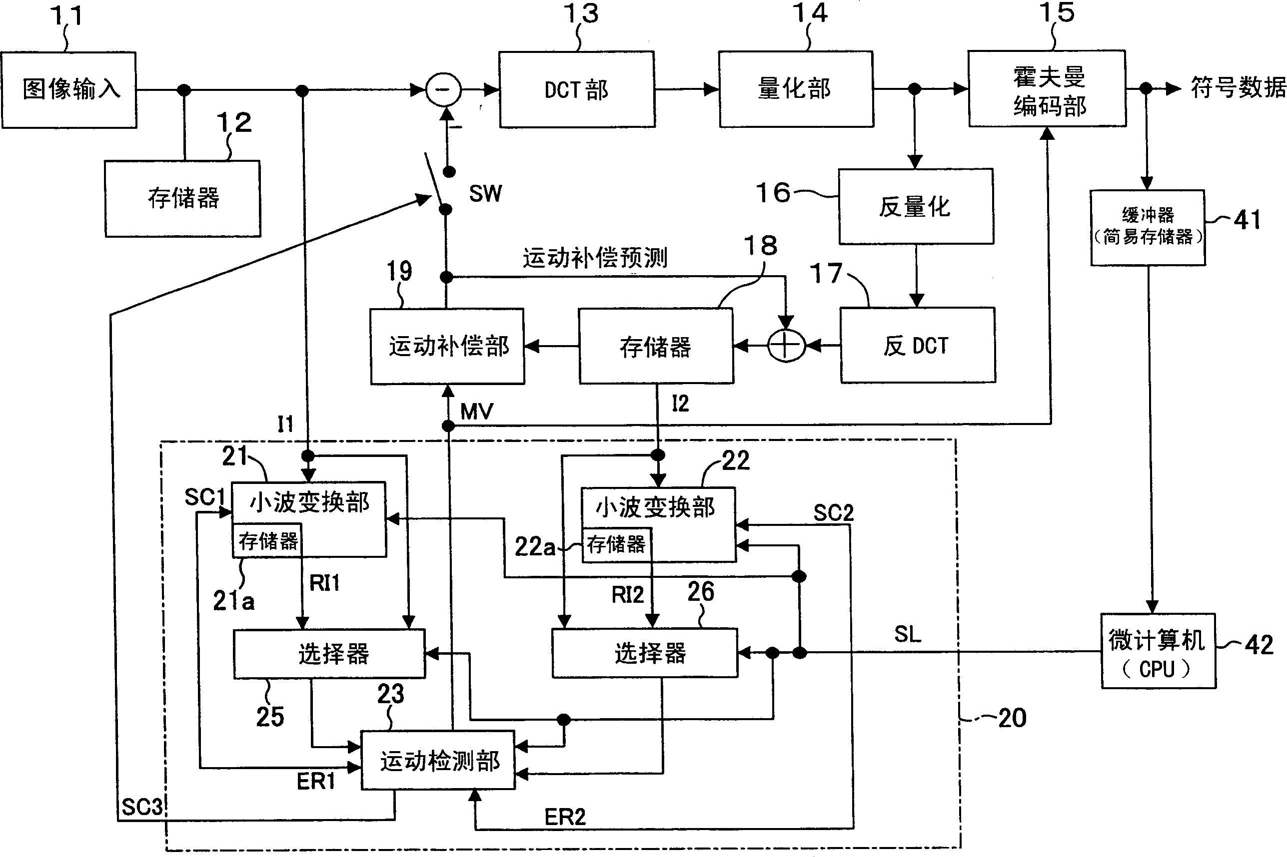
[0059] figure 1 A block diagram showing the configuration of the image coding apparatus according to the first embodiment of the present invention. exist figure 1 In this case, the image signal input from the image input unit 11 is temporarily stored in the frame memory 12 . In intra-frame encoding, the image signal stored in the frame memory 12 is encoded by the DCT unit 13 , the quantization unit 14 , and the Huffman encoding unit 15 , and transmitted as encoded data. At this time, the frame data output from the quantization unit 14 is decoded by the inverse quantization unit 16 and the inverse DCT unit 17 , and stored in the frame memory 18 . On the other hand, during inter-frame encoding, the image signal stored in the frame memory 12 is calculated and compared with the motion-compensated reference image, that is, the reference image stored in the frame memory 18 is subjected to motion compensation by the motion compensation unit 19. difference between the images. Th...
no. 2 Embodiment approach
[0092] Figure 5 A block diagram showing the configuration of an image coding apparatus according to the second embodiment of the present invention. exist Figure 5 neutralize figure 1 common building blocks, using and figure 1 The same symbols are used, and detailed explanations thereof are omitted here. exist Figure 5 In the structure, the bit rate counter 31 that counts the number of symbols (bit flow) processed by the Huffman coding section 15 is provided, and the number of repetitions of wavelet transformation in the motion detection block 20A is passed through the output of the bit flow counter 31. Control, in this way, the rate control of the amount of symbols can be realized.
[0093] Generally, when the bit rate is lowered, the quantization factor may be increased, but the image quality may be deteriorated in this case. On the other hand, in this embodiment, the bit rate can be reduced by increasing the detection probability of the motion vector and reducing ...
no. 3 Embodiment approach
[0102] In the third embodiment of the present invention, when judging whether to perform frequency conversion during motion detection, it is detected whether there is frequency conversion for a macroblock that has been processed earlier than the motion detection target macroblock in time, and this judgment is added . The configuration example of the image encoding device of this embodiment is basically the same as Figure 5 The same, but the motion detection block 20A behaves differently.
[0103] Regarding the image coding method of this embodiment, it is also basically as follows Figure 10 shown. Figure 7 Indicates that in this embodiment Figure 10 The process of step S1, that is, the flow chart of the motion detection block 20A. exist Figure 7 in Figure 6 Step S21 was added to the flow chart of . That is, as a pre-processing of motion detection, in a macroblock of a frame temporally earlier than the current image, or in an adjacent coded macroblock, the motion d...
PUM
 Abstract
Description
Claims
Application Information