Braking torque self-detecting circuit for elevator brake

A technology for elevator brakes and braking torque, applied in the direction of force/torque/power measuring instruments, instruments, measuring devices, etc., which can solve the problems that the braking torque cannot be detected, the braking torque self-test function cannot be realized, etc.

Active Publication Date: 2014-05-28
SHIJIAZHUANG WULON BRAKE
View PDF10 Cites 7 Cited by
  • Summary
  • Abstract
  • Description
  • Claims
  • Application Information

AI Technical Summary

Problems solved by technology

However, the safety control loop of the existing elevator brake cannot detect the braking torque of the s

Method used


Image

  • Braking torque self-detecting circuit for elevator brake
  • Braking torque self-detecting circuit for elevator brake
  • Braking torque self-detecting circuit for elevator brake

Examples


Embodiment 1

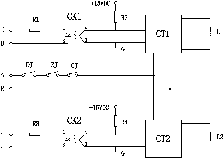
[0018] This embodiment is aimed at the circuit structure configured by dual brake controllers. Such as figure 1 As shown, the input terminals of the two brake controllers CT1 and CT2 are connected to the brake circuit (the two terminal points of the brake circuit are marked as A and B), and the door lock relay DJ and the brake relay are connected in series in the brake circuit. Gate relay ZJ and run contactor CJ. The working voltage of the brake circuit is applied to both ends of A and B, and the voltage can be AC ​​110 / 220V or DC 110 / 220V.

[0019] The output terminals of the two brake controllers CT1 and CT2 are respectively connected to an electromagnetic coil L1 and L2. Control terminals are respectively provided on the two brake controllers CT1 and CT2 to control the actions of the brake controllers. Connect a level control loop to the control terminals of the two brake controllers CT1 and CT2 (the two terminal points of one level control loop are marked as C and D, an...

Embodiment 2

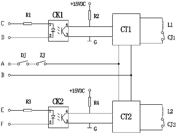
[0025] This embodiment is also aimed at the circuit structure configured by dual brake controllers. Such as figure 2 As shown, its circuit structure and working principle are basically the same as that of Embodiment 1, the difference is that the running contactor CJ is removed from the brake circuit and becomes two, which are respectively set in the circuits of the electromagnetic coils L1 and L2 , that is, after the electromagnetic coil L1 is connected in series with the running contactor CJ1, and the electromagnetic coil L2 is connected in series with the running contactor CJ2, they are respectively connected to the output ends of the corresponding brake controllers CT1 and CT2.

Embodiment 3

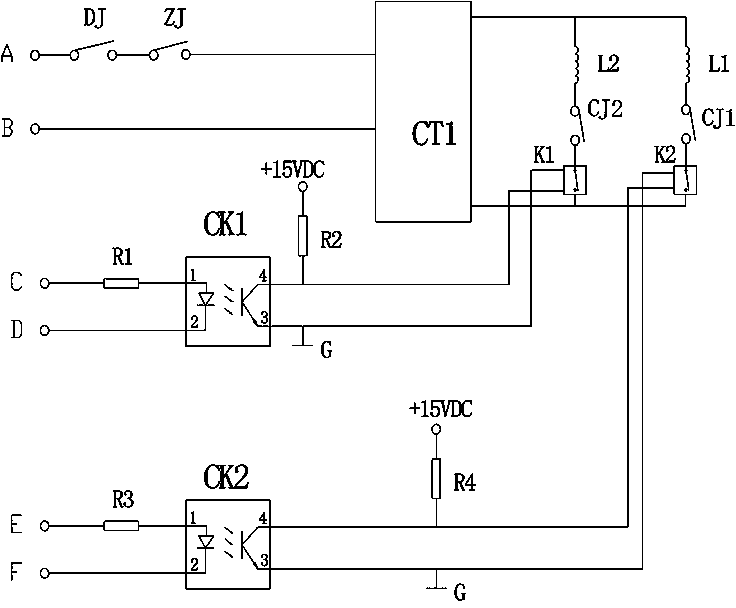
[0027] This embodiment is for a circuit structure configured with a single brake controller. Such as Figure 4 As shown, the brake circuit is connected to the input end of the brake controller CT1 (the two terminals of the brake circuit are marked as A and B), and the brake controller CT can adopt a conventional control circuit structure. A door lock relay DJ, a brake relay ZJ and a running contactor CJ are connected in series in the brake circuit. The working voltage of the brake circuit is applied to both ends of A and B, and the voltage can be AC ​​110 / 220V or DC 110 / 220V.

[0028] Two electromagnetic coils L1, L2 connected in parallel are connected to the output terminal of the brake controller CT1. A control switch K1, K2 is connected in series on each electromagnetic coil branch, and a level control loop is respectively connected to the action control ends of the two control switches K1, K2 (the two terminal points of a level control loop are marked as C, D, the two t...


PUM


Abstract

The invention relates to a braking torque self-detecting circuit for an elevator brake. The braking torque self-detecting circuit is characterized in that a band-type brake loop is connected to the input ends of two brake controllers, the output end of each brake controller is connected with an electromagnetic coil, the two brake controllers are respectively provided with a control end controlling the action of the corresponding brake controller, the control ends are connected with level control loops respectively connected with an isolation control switch, and the input ends of the level control loops are used for being connected with an upper computer of an elevator control cabinet and receiving a braking torque self-detecting order sent by the upper computer. According to the braking torque self-detecting circuit, the separation state of not supplying electricity to the brake while an elevator motor is powered on can be achieved, whether the braking torque of the brake meets the requirement or not can be judged by judging whether the motor can rotate or not, or the braking torque of the elevator brake can be automatically detected by respectively judging whether the braking torque on each side of the brake meets the requirement or not so that the self-detecting of the braking torque of the elevator brake can be achieved.

Description

technical field [0001] The invention relates to a brake detection control circuit, in particular to an elevator brake brake torque self-detection circuit. Background technique [0002] In order to improve the safety factor of the elevator operation, the existing elevator brakes are required to be equipped with a dual-circuit braking system, that is, two sets of braking electromagnets are installed, and the electromagnetic coils in the two sets of braking electromagnets can be connected in parallel to a braking system. On the controller, there is a brake controller for control; it can also be connected to a brake controller, and the two brake controllers are controlled separately, but the two brake controllers are connected to a brake circuit, and a brake controller is controlled by a brake controller. The brake circuit is controlled. [0003] With the development of elevator technology, it is required that all components of the elevator should develop in a safe direction wi...

Claims


Application Information

Patent Timeline
IPC IPC(8): B66B5/00G01L5/28
Inventor 韩伍林侯增敏
Owner SHIJIAZHUANG WULON BRAKE
Why Eureka
Try Eureka