
Touch scanning method and device

A technology of touch events and scanning methods, which is applied in the input/output process of instruments, electrical digital data processing, and data processing, etc., can solve the problems of slow touch response, touch disconnection, touch error, etc., and achieves reduced scanning range, The effect of reducing touch delay and reducing energy consumption

Inactive Publication Date: 2014-05-28
HISENSE VISUAL TECH CO LTD
View PDF4 Cites 14 Cited by
  • Summary
  • Abstract
  • Description
  • Claims
  • Application Information

AI Technical Summary

Problems solved by technology

[0006] The present invention provides a touch event scanning method and device, which are used to solve the problem of touch delay caused by too long scan period in the prior art, as well as slow touch response, touch disconnection and touch delay caused by touch delay. wrong question

Method used


Image

  • Touch scanning method and device
  • Touch scanning method and device
  • Touch scanning method and device

Examples


Embodiment Construction

[0050]The touch event scanning method proposed by the present invention will be described in more detail below with reference to the drawings and embodiments.

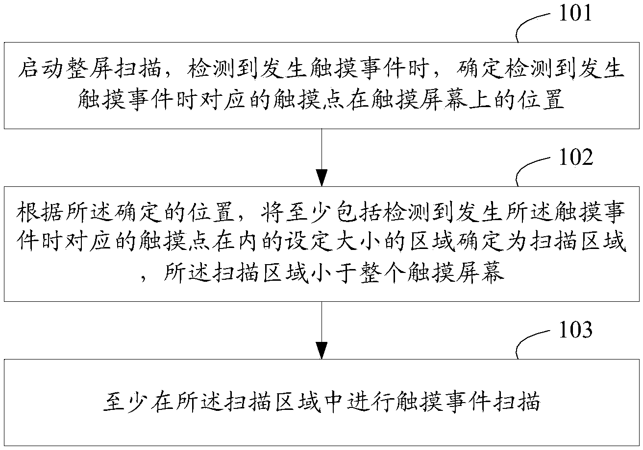
[0051] A touch event scanning method provided by the present invention, such as figure 2 shown, including:

[0052] Step 101, start scanning the entire screen, and when a touch event is detected, determine the position of the corresponding touch point on the touch screen when the touch event is detected.

[0053] Taking the infrared touch screen as an example, when a touch event occurs, the touch event may block a pair of infrared tubes in the horizontal and vertical directions, or block multiple pairs of infrared tubes. If the horizontally blocked pair of infrared tubes and the vertically blocked If the point at the intersection of a pair of blocked infrared tubes is called a touch point, then a touch event may correspond to one or more touch points. In the initial stage, start the whole screen scan, that is, use t...


PUM


Abstract

The invention discloses a touch scanning method and device. The method includes: starting screen scanning, and when detecting a touch, determining the position of a corresponding touch point on a touch screen when the touch occurs; according to the determined position, determining a set-sized area, including the corresponding touch point when the touch occurs, as a scan area which is smaller than the touch screen; performing touch scanning at least in the scan area. The method and device has the advantages that the touch in the scan area can be scanned by determining the scan area smaller than the touch screen, touch scanning period is shortened, the scan area is updated in real time with sliding of the touch, the problems such as low touch response speed, discontinuous touch and touch errors caused by touch delay are solved, and meanwhile, the scan range is narrowed, and accordingly energy consumption is lowered and energy loss is low.

Description

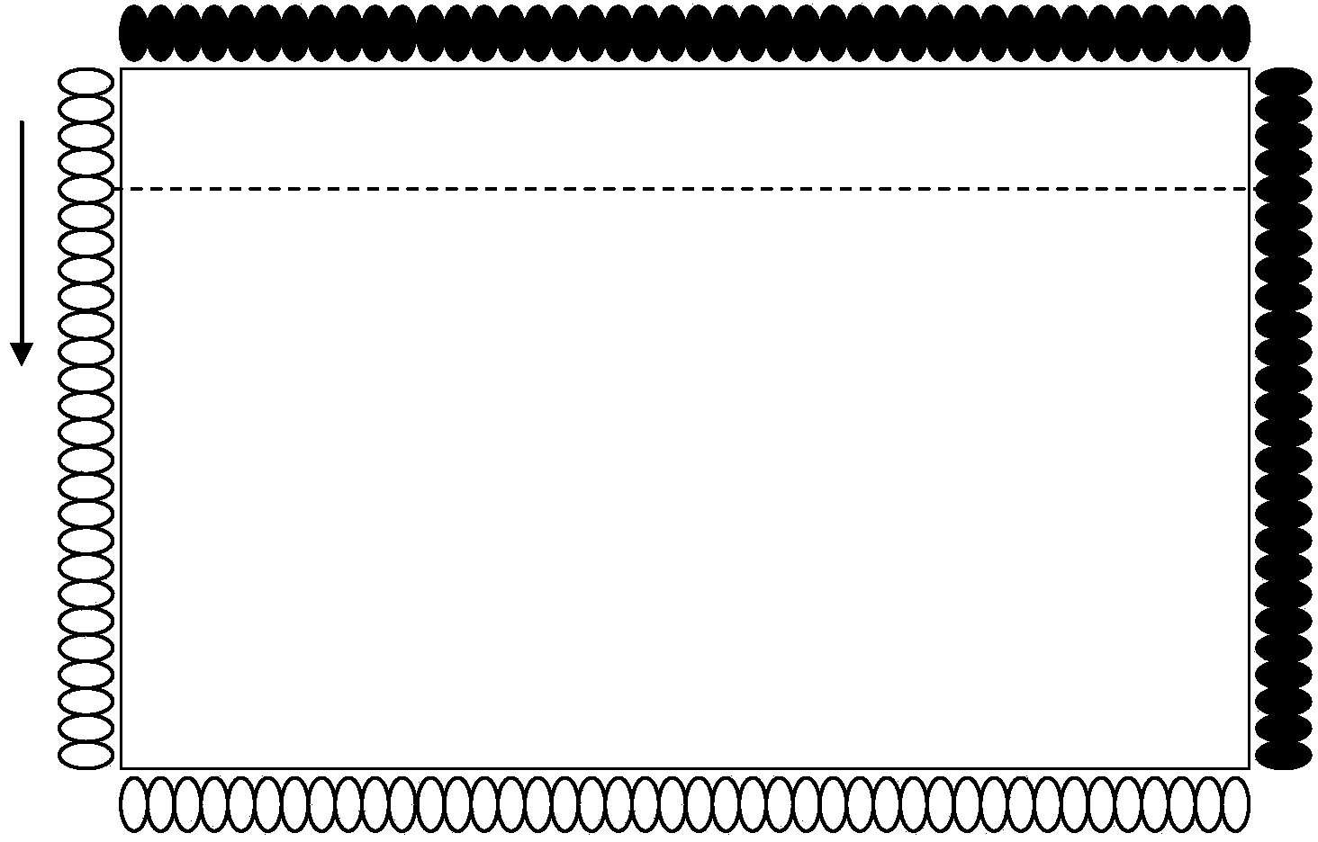
technical field [0001] The present invention relates to the technical field of touch event scanning, in particular to a touch event scanning method and device. Background technique [0002] At present, the infrared touch technology based on the infrared touch frame is usually used to realize touch control on a large display screen; that is, an infrared emitting tube and an infrared receiving tube are installed on the edge of a rectangular touch screen, such as figure 1 As shown, the infrared tubes on the left edge and the lower edge are infrared emitting tubes, the infrared tubes on the upper edge and the right edge are infrared receiving tubes, and there is a one-to-one correspondence between the horizontally and vertically opposite transmitting tubes and receiving tubes ( Such as figure 1 The two infrared tubes connected by the dotted line are a pair). Starting from a certain infrared emitting tube, according to the set sequence, such as starting from the counterclockwis...

Claims


Application Information

Patent Timeline
Patent Type & Authority Applications(China)
IPC IPC(8): G06F3/042
CPCG06F3/041661G06F3/0428G06F3/0412G06F3/0421
Inventor 张旭王守帅
Owner HISENSE VISUAL TECH CO LTD
Learn More