
Door brace

A door bracket and wall-joining technology, which is applied in the field of door brackets, can solve problems such as tripping and easy connection failure, and achieve the effect of being easy to carry and improving portability

Active Publication Date: 2014-05-28
PENN ELCOM CORP +1
View PDF7 Cites 12 Cited by
  • Summary
  • Abstract
  • Description
  • Claims
  • Application Information

AI Technical Summary

Problems solved by technology

While this is an improvement over using a chair, the connection between the rod and doorknob is prone to failure, and the rod significantly extends beyond the door, presenting a tripping hazard

Method used


Image

  • Door brace
  • Door brace
  • Door brace

Examples


Embodiment Construction

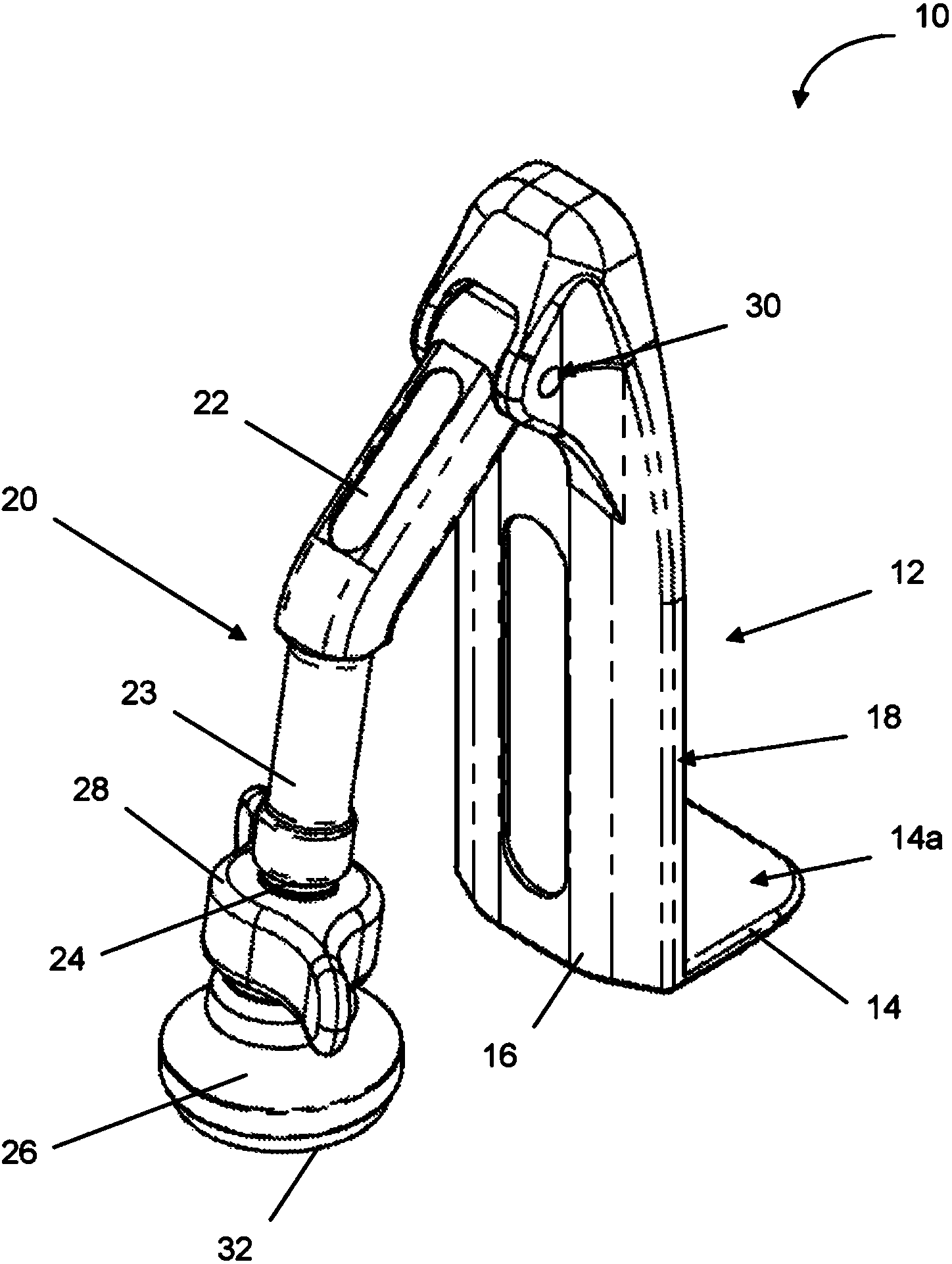
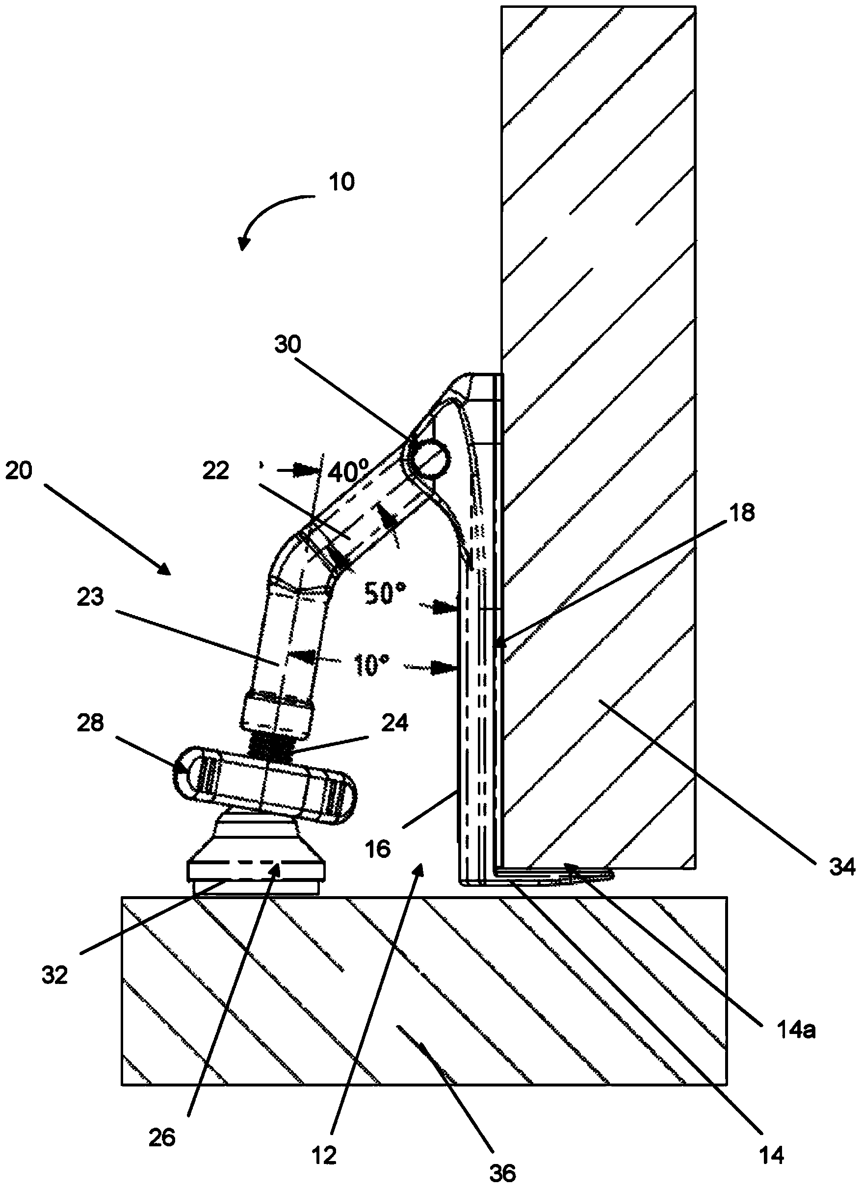
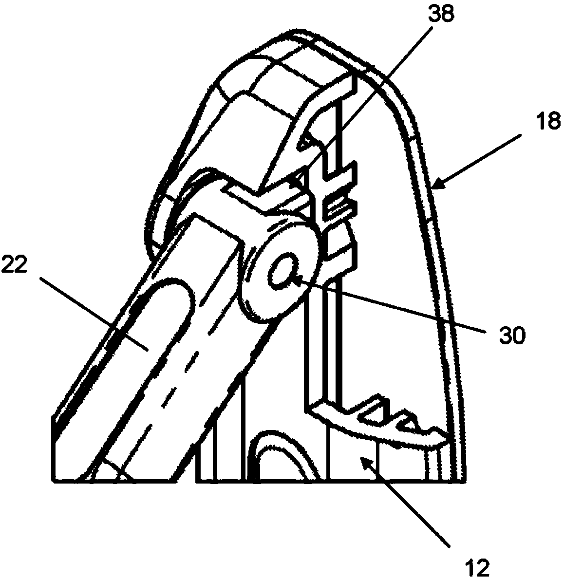
[0026] refer to Figures 1 to 4 , The first embodiment of the present invention provides a door bracket 10 comprising a door engaging member 12 , an angled leg 20 , an engaging foot 26 and a hinge stop 38 .

[0027] The door engaging member 12 includes a bottom flange 14 and an engaging wall 16 . Bottom flange 14 is adapted to be positioned below the bottom edge of door 34, as figure 2 shown. The bottom flange includes a textured surface 14a adapted to engage the bottom edge of the door 34 to prevent the door bracket from sliding out from under the door, for example, if the door is moved rapidly.

[0028] The engagement wall 16 extends substantially upwardly from the bottom flange 14 . One face 18 of the engaging wall is adapted to abut against the part on one side of the door, at the bottom edge, as figure 2 shown. In this example, the engagement wall 16 and the bottom flange 14 together define a substantially L-shaped recess for receiving a portion of the door at its ...


PUM


Abstract

A door brace (10) comprising :an engagement member (12)comprising a bottom flange(14) comprising one face comprising a textured surface (14a) to engage with a door (34); an angled leg (20) comprising a first section(22) hingedly connected at one end to the wall and a second section (23) extending from the first section at a first angle, the leg being movable between a stowed position and an extended position in which the first section makes a second angle, larger than the first angle, to the wall; an engagement foot (26) pivotably mounted on a mounting element (24) having an adjustable length; and a hinge stop configured to prevent the leg moving beyond a maximum extended position. Wherein, in an extended position, the second section of the leg extends at a third angle to the wall equal to the difference between the second and first angles and the engagement foot causes a clamping force to be applied to the door.

Description

technical field [0001] The invention relates to a door bracket. Background technique [0002] In many cases it may be desirable to increase the sense of security of the door, for example by installing stronger locks or additional bolts around the door at additional locking points. However, it is not always possible or convenient to install such permanent pieces on the door of, for example, a rented house or office, hotel or hostel-style dormitory, or student accommodation. In these cases, it is desirable to increase the sense of security of the door through the use of non-permanent devices. One known method is to jam the chair under the door handle, but unless the chair is of proper size and construction, the door cannot be held in place for long by this method. One solution that has been proposed extends the method of blocking the door to close it by positioning the rod at an angle between the door handle and the ground behind the door. While this is an improvement over ...

Claims


Application Information

Patent Timeline
IPC IPC(8): E05C17/44E05C17/54E05C19/00E05C19/18
CPCE05C17/44E05C19/004E05C17/54E05C19/182E05C17/443Y10T292/34Y10T292/67E05C17/48E05C17/50E05C19/18E05C19/188
Inventor J.哈顿史蒂夫.圣詹姆斯
Owner PENN ELCOM CORP
Learn More