Laser marking device capable of feeding and discharging materials automatically

A laser marking equipment and automatic loading and unloading technology, applied in printing and other directions, can solve the problems of sorting and placement of marking products, marking position deviation, time-consuming and labor-intensive, etc., to reduce investment, improve marking efficiency, and improve marking efficiency. The effect of standard efficiency

Active Publication Date: 2014-06-04
深圳市艾雷激光科技有限公司
View PDF15 Cites 25 Cited by
  • Summary
  • Abstract
  • Description
  • Claims
  • Application Information

AI Technical Summary

Problems solved by technology

[0005] However, the existing automatic loading and unloading laser marking equipment is equipped with a machine base, and a laser engraving mechanism is provided on the machine base. Since the marking products are placed in disorder, the transportation equipment cannot arrange the marking products correctly, so only by relying on The operator manually places the marking product under the laser engraving mechanism for marking, and each device requires an operator to be responsible for the control. The whole process is time-consuming and laborious, and manual placement of the marking product is also prone to deviation, resulting in deviation of the marking position. Therefore, there is an urgent need for an automatic loading and unloading laser marking equipment that can solve the above problems

Method used


Image

  • Laser marking device capable of feeding and discharging materials automatically
  • Laser marking device capable of feeding and discharging materials automatically
  • Laser marking device capable of feeding and discharging materials automatically

Examples


Embodiment Construction

[0036] The present invention will be described in further detail below in conjunction with the accompanying drawings and specific embodiments.

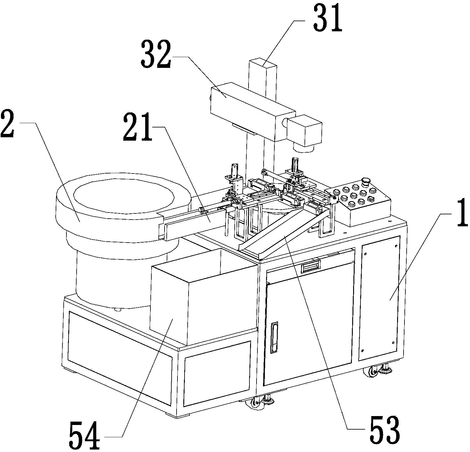
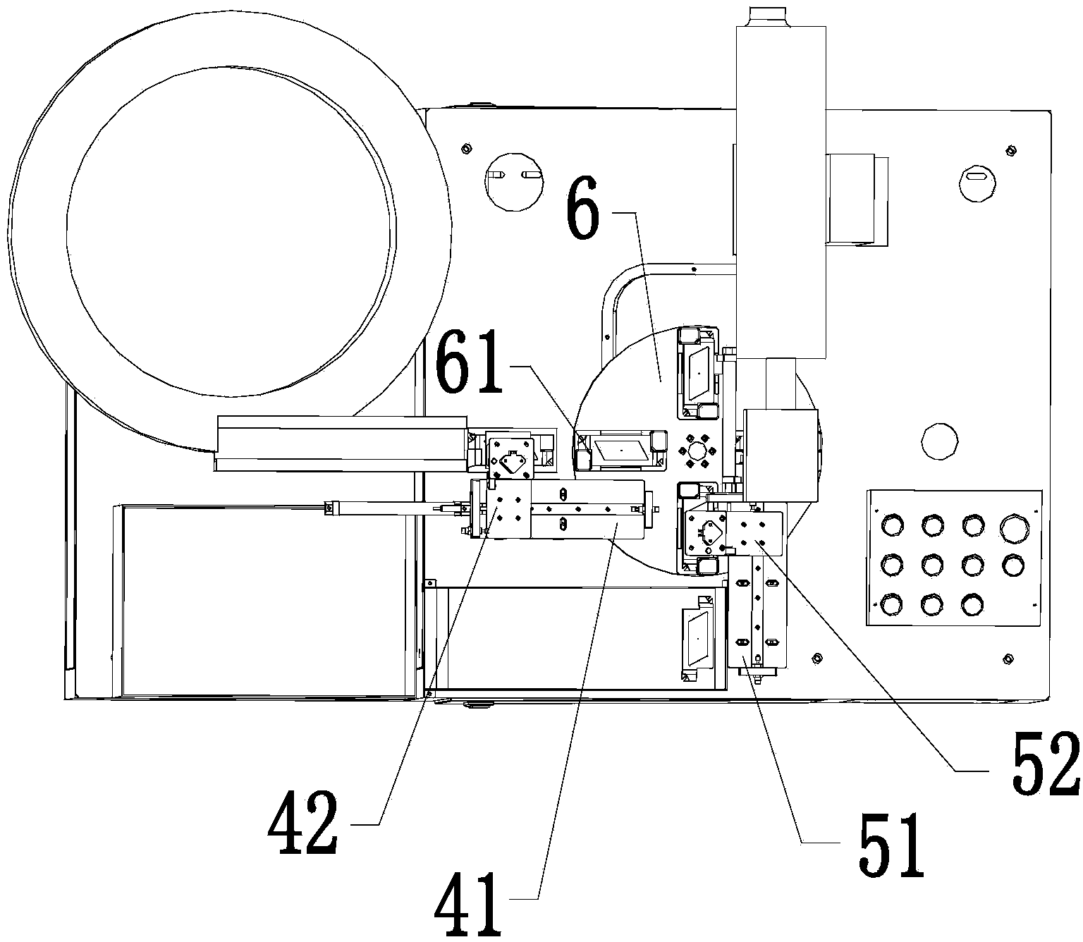
[0037] As shown in Figures 1 to 4, the automatic loading and unloading laser marking equipment of the present invention includes a machine base 1, a vibrating plate 2, a laser engraving mechanism and a central processing unit for controlling the work of the automatic loading and unloading laser marking equipment; The disc 2 is arranged on the machine base 1, and the vibrating disc 2 is provided with a conveying track 21; the said machine base 1 is provided with a feeding mechanism, a feeding mechanism and a rotary disk 6 that can rotate around the center; At the blanking place of the conveying track 21; the rotary disk 6 is located at the blanking place of the reclaiming mechanism, and the rotary disk 6 is provided with four discharging racks 61, and the laser engraving mechanism is placed at the punching place of the rotary disk 6. a...


PUM


Abstract

The invention discloses a laser marking device capable of feeding and discharging materials automatically and belongs to the field of laser marking. The laser marking device capable of feeding and discharging the materials automatically comprises a vibrating disk, a machine base, a laser etching mechanism and a central processing unit which controls the laser marking device capable of feeding and discharging the materials automatically to operate. The vibrating disk is provided with a conveying track. The machine base is provided with a material taking mechanism, a discharging mechanism and a rotating disk which can rotate around the center. The material taking mechanism is arranged at the discharging position of the conveying track. The rotating disk is arranged at the discharging position of the material taking mechanism. The rotating disk is provided with multiple carrying frames. The laser etching mechanism is arranged above the marking position of the rotating disk. The discharging mechanism is arranged at the discharging position of the rotating disk. According to the laser marking device capable of feeding and discharging the materials automatically, the vibrating disk is used for solving the problem that an existing laser marking device cannot adjust marked products to be conveyed in a correct state; as a result, full-automatic marking through the laser marking device is realized, marking efficiency is greatly improved, and labor cost is reduced.

Description

[0001] technical field [0002] The invention relates to a marking device, in particular to a laser marking device. [0003] Background technique [0004] Laser marking is the use of laser beams to make permanent marks on various material surfaces. The effect of marking is to expose the deep material through the evaporation of the surface material, or to "carve" traces through the chemical and physical changes of the surface material through light energy, or to burn part of the material through light energy, showing the required etching. pattern, text. Laser marking has the advantages of fast marking speed, good continuous working stability, and positioning accuracy. It is widely used in the marking of graphics and text in various fields such as electronics, hardware, aviation components, auto parts, and metal signs. [0005] However, the existing automatic loading and unloading laser marking equipment is equipped with a machine base, and a laser engraving mechanism is pr...

Claims


Application Information

Patent Timeline
Patent Type & Authority Applications(China)
IPC IPC(8): B41J2/435
Inventor 唐群生杨志画
Owner 深圳市艾雷激光科技有限公司
Why Eureka
Try Eureka