Laser stirring friction welding method and device thereof

A friction stir, welding method technology, applied in welding equipment, welding/welding/cutting items, manufacturing tools, etc., can solve problems such as workpiece deformation, sensitivity to welding heat input, instability, etc.

Active Publication Date: 2014-06-11
SHANGHAI AEROSPACE EQUIP MFG GENERAL FACTORY
View PDF5 Cites 19 Cited by
  • Summary
  • Abstract
  • Description
  • Claims
  • Application Information

AI Technical Summary

Problems solved by technology

[0005] For the selection of auxiliary heat source in the high-speed micro-stir friction welding process, two issues must be considered: one is the heat flux of the welding heat source. Micro-stir friction welding is mainly for the welding of thin-walled components, which are very sensitive to welding heat input. Increasing the heating range will lead to serious deformation of the workpiece, or even local instability; second, the application of welding auxiliary heat sources must meet the stability requirements of the high-speed rotation and high-speed movement of the welding tool
However, the application of the traditional auxiliary heat source must solve a series of problems caused by the characteristics of the micro-friction stir welding process, and it is urgent to develop a new composite heat source welding method for the solid-phase connection of ultra-thin-walled components.

Method used


Image

  • Laser stirring friction welding method and device thereof
  • Laser stirring friction welding method and device thereof

Examples


Embodiment Construction

[0029] The technical solutions of the present invention are described below through preferred embodiments, but the following embodiments cannot limit the protection scope of the present invention.

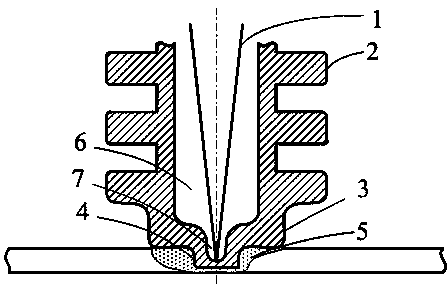
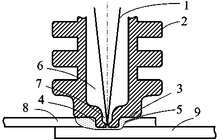
[0030] Such as figure 1 and figure 2 As shown, a laser friction stir welding method, including a laser beam (1), a welding tool and a weld, is characterized in that the welding tool at least includes a stirring needle (4), a shaft shoulder (3), a cooling fin (2 ) and a hollow cavity (6), when welding, the stirring needle (4) is inserted into the weld and rotates and advances along the weld seam, the laser beam (1) passes through the hollow cavity (6) of the welding tool to the stirring needle ( 4) Heating, the stirring needle (4) absorbs the light energy of the laser beam (1) and instantly converts it into heat energy and conducts it to the weld material for welding.

[0031] In this embodiment, the diameter of the small hole cavity (7) of the stirring pin is 0.3~1mm, the rotati...


PUM

PropertyMeasurementUnit
diameteraaaaaaaaaa
diameteraaaaaaaaaa
diameteraaaaaaaaaa

Abstract

The invention relates to a laser stirring friction welding method which includes a laser beam, a welding tool and a welded object. The welding tool at least comprises a stirring needle, a shaft shoulder, radiating fins and a hollow inner cavity. During welding, the stirring needle is inserted into the welded object to rotate and advance along a welding gap, the laser beam heats the stirring needle through the hollow inner cavity of the welding tool, and the stirring needle absorbs optical energy of the laser beam, converts the optical energy into heat energy instantaneously and transfers the heat energy to the welded object to conduct welding. When the laser beam heats the stirring needle through the hollow inner cavity of the welding tool, the hollow inner cavity is filled with protection gas which is helium, and the helium is high ionization energy helium. By means of the method, the problem that a micro-size stirring tool used in traditional stirring friction welding is insufficient in heat production is solved, and welding quality and stability of laser direct welding of thin wall aluminum alloy are improved.

Description

technical field [0001] The invention relates to the technical field of solid phase welding, in particular to a laser friction stir welding method and a device thereof. Background technique [0002] In the field of friction stir welding technology, the composite heat source welding method has become an effective means to extend the scope of application of this technology. By applying additional welding energy, it can effectively soften the material to be welded and reduce the upsetting force and forward force required for welding. These composite welding methods are not effective for the traditional friction stir welding of aluminum alloys, because the traditional friction stir welding equipment can obtain good forming as long as it has enough rigidity and can provide the upsetting force and forward force required for welding. of the weld. [0003] For the welding of small components and ultra-thin-walled components, the length of the stirring needle is generally 0.1~0....

Claims


Application Information

Patent Timeline
Patent Type & Authority Applications(China)
IPC IPC(8): B23K28/02
CPCB23K28/02B23K2103/08B23K2103/10
Inventor 封小松郭立杰何文松刘明芳
Owner SHANGHAI AEROSPACE EQUIP MFG GENERAL FACTORY
Why Eureka
Try Eureka