Engine hydraulic suspension limiting structure
A technology of hydraulic suspension and limit structure, which is applied in the direction of power plant, jet propulsion device, internal combustion propulsion device, etc. It can solve the problem of large displacement of powertrain, collision of spoiler decoupling diaphragm 6, and unfavorable vehicle layout to save space, improve comfort and safety, and avoid abnormal noise or failure
- Summary
- Abstract
- Description
- Claims
- Application Information
AI Technical Summary
Problems solved by technology
Method used
Image

Examples
Embodiment Construction
[0016] The present invention will be further described below in conjunction with accompanying drawing and embodiment:
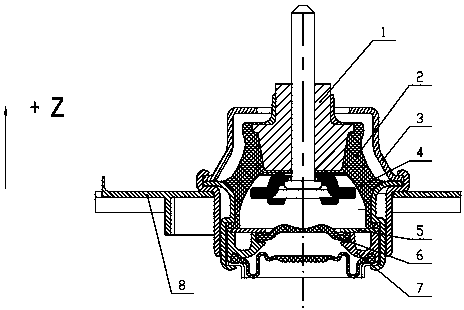
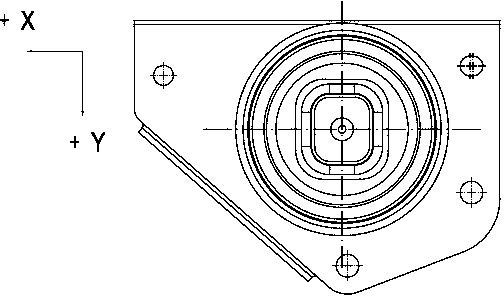
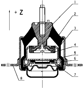
[0017] see image 3 with Figure 4 , the limit structure of the engine hydraulic mount includes active side bracket 1, rubber main spring 2, limit structure 3, spoiler plate 4, flow channel cover 5, decoupling diaphragm 6, aluminum flow channel 7 and passive side bracket 8. The upper end of the active side bracket 1 is used to connect with the powertrain, and the part near the lower end is vulcanized together with the rubber main spring 2 , and the active side bracket 1 and the passive side bracket 8 are connected through the rubber main spring 2 . The lower end of the active side bracket 1 extends into the passive side bracket 8 of the hydraulic suspension, and the spoiler 4 is riveted and fixed, and a layer of rubber is vulcanized on the surface of the spoiler. The limit structure 3 is set in the passive side bracket 8, the upper end of which is sleeved ...
PUM
 Abstract
Description
Claims
Application Information
 - R&D
- Intellectual Property
- Life Sciences
- Materials
- Tech Scout
- Unparalleled Data Quality
- Higher Quality Content
- 60% Fewer Hallucinations
Browse by: Latest US Patents, China's latest patents, Technical Efficacy Thesaurus, Application Domain, Technology Topic, Popular Technical Reports.
© 2025 PatSnap. All rights reserved.Legal|Privacy policy|Modern Slavery Act Transparency Statement|Sitemap|About US| Contact US: help@patsnap.com