
A-column reinforcing plate connection structure

A technology of connecting structure and reinforcing plate, applied in the directions of superstructure, sub-assembly of superstructure, transportation and packaging, etc., can solve the problems of increased cost, steering wheel, instrument panel vibration, insufficient fixing strength and rigidity of instrument panel beam bracket, etc. Achieve the effect of avoiding increase, improving modal, and avoiding cost

Inactive Publication Date: 2014-06-11
SAIC-GM-WULING AUTOMOBILE CO LTD
View PDF7 Cites 4 Cited by
  • Summary
  • Abstract
  • Description
  • Claims
  • Application Information

AI Technical Summary

Problems solved by technology

[0003] The A-pillar reinforcement plate is a part used to strengthen the strength of the A-pillar. There are two main connection structures for the existing A-pillar reinforcement plate. Together, its disadvantages are: the fixing strength and rigidity of the instrument panel crossbeam bracket are insufficient, which will easily cause the steering wheel and instrument panel to vibrate, which will affect the perceived quality of the vehicle; Plate beam bracket connection, its defect is: increase a reinforcement plate, increase the cost of the body in white

Method used


Image

  • A-column reinforcing plate connection structure
  • A-column reinforcing plate connection structure
  • A-column reinforcing plate connection structure

Examples


Embodiment Construction

[0016] The present invention will be further described below in conjunction with the accompanying drawings and specific embodiments.

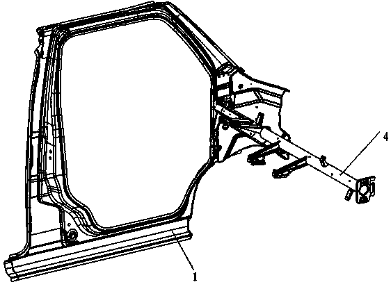
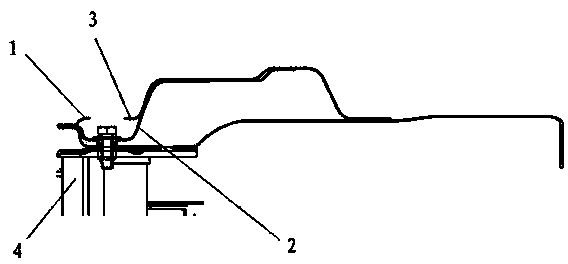
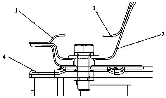
[0017] Figure 1 to Figure 3 The reference numerals in the figure are: front side wall outer panel 1; A-pillar reinforcement plate 2; front side panel 3; instrument panel beam bracket 4.

[0018] Such as Figure 1 to Figure 3 As shown, an A-pillar reinforcement panel connection structure includes a front side wall outer panel 1, an A-pillar reinforcement panel 2, a front side panel 3 and an instrument panel beam bracket 4, wherein the A-pillar reinforcement panel 2 is connected to the front The side wall outer panel 1 is connected, the A-pillar reinforcement plate 2 is provided with a flange, and the front side panel 3 and the instrument panel beam bracket 4 are respectively connected with the flange.

[0019] Such as Figure 1 to Figure 3 As shown, the instrument panel beam bracket 4 is connected to the flange through fasteners.

[0020] S...


PUM


Abstract

The invention relates to automobile bodies, in particular to an A-column reinforcing plate connection structure in the automobile bodies. The A-column reinforcing plate connection structure comprises a front peripheral plate, an A-column reinforcing plate, a front lateral plate and a dashboard crossbeam support. The A-column reinforcing plate is connected with the front peripheral plate and provided with a flanging, and the front lateral plate and the dashboard crossbeam support are respectively connected with the flanging. The A-column reinforcing plate connection structure has the advantages that without increasing parts, the flanging is additionally arranged on the A-column reinforcing plate which is connected with the front lateral plate and the dashboard crossbeam support through the flanging, and consequently strength of the front lateral plate and the dashboard crossbeam support can be improved to enable the front lateral plate and the dashboard crossbeam support to be firmer, modality of the automobile body is improved, and cost increase is avoided.

Description

technical field [0001] The invention relates to an automobile body, in particular to an A-pillar reinforcing plate connection structure in the automobile body. Background technique [0002] The A-pillar is the connecting column connecting the roof and the front cabin on the left and right fronts. Generally, there are three types of pillars in the body of a car. From front to back, they are the front pillar (A pillar), the middle pillar (B pillar), and the rear pillar (C pillar). For cars, in addition to supporting the column, it also acts as a door frame. [0003] The A-pillar reinforcement plate is a part used to strengthen the strength of the A-pillar. There are two main connection structures for the existing A-pillar reinforcement plate. Together, its disadvantages are: the fixing strength and rigidity of the instrument panel crossbeam bracket are insufficient, which will easily cause the steering wheel and instrument panel to vibrate, which will affect the perceived qu...

Claims


Application Information

Patent Timeline
IPC IPC(8): B62D25/04
Inventor 许冰黄岗朱灯宏伍升安
Owner SAIC-GM-WULING AUTOMOBILE CO LTD
Learn More