Gauge board beam installation component

A technology for installing components and instrument panels, applied in vehicle components, transportation and packaging, superstructure, etc., can solve problems such as affecting user use and perception, insufficient rigidity of instrument panel beams, installation rigidity modal steering wheel and instrument panel jitter, etc.

Active Publication Date: 2017-01-25
SAIC-GM-WULING AUTOMOBILE CO LTD
View PDF6 Cites 3 Cited by
  • Summary
  • Abstract
  • Description
  • Claims
  • Application Information

AI Technical Summary

Problems solved by technology

[0002] In the existing body-in-white structure, the dashboard crossbeam is the mounting bracket for the dashboard components of the vehicle. Insufficient installation rigidity modal will easily cause the vibration of the steering wheel and dashboard, which directly affects the user's use and perception
[0003] 1. The instrument panel beam is only installed on the left and right front side panels (such as figure 1 As shown), the support force and limit of the instrument panel beam are provided through the left and right front side panels and reinforcement plates (generally the front side panel is 0.8mm, the reinforcement plate is 1.2mm, and the total thickness is about 2.0mm); the rigidity of the instrument panel beam is insufficient. Steering wheel and dashboard vibrate at lower speeds
[0004] 2. In addition to being connected to the left and right front side panels, the crossbeam of the instrument panel connects the two assemblies of the dash panel and the front floor with a bracket in the middle. This structure effectively improves the stiffness and mode of the crossbeam of the instrument panel. The panel crossbeam needs to be connected with 4 00-level assemblies, and the installation points of the 5 assemblies require high precision, which is prone to blocking holes in the middle bracket of the instrument panel and the body parts, making it difficult to match

Method used


Image

  • Gauge board beam installation component
  • Gauge board beam installation component
  • Gauge board beam installation component

Examples


Embodiment Construction

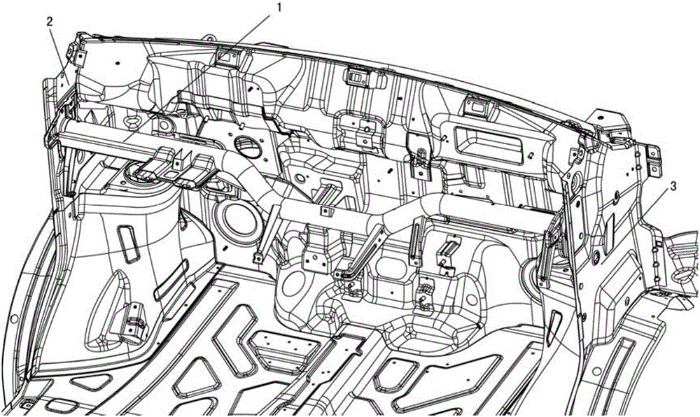
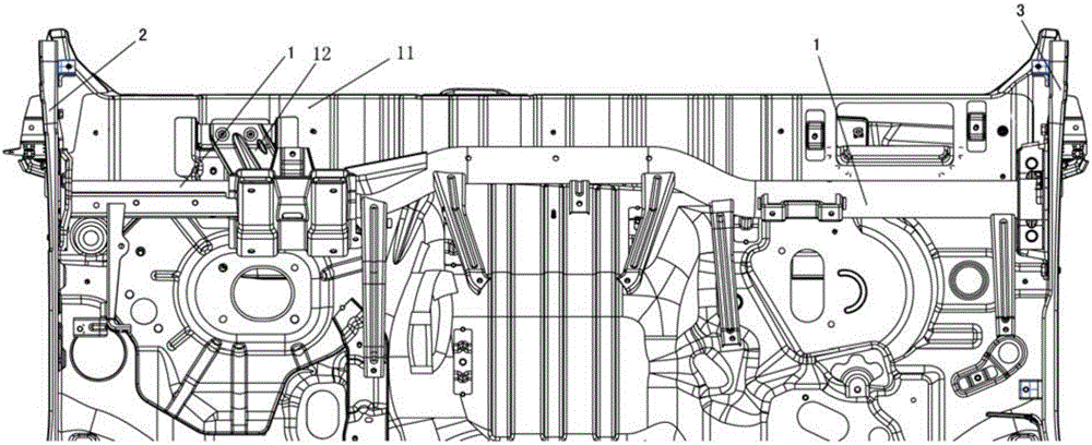
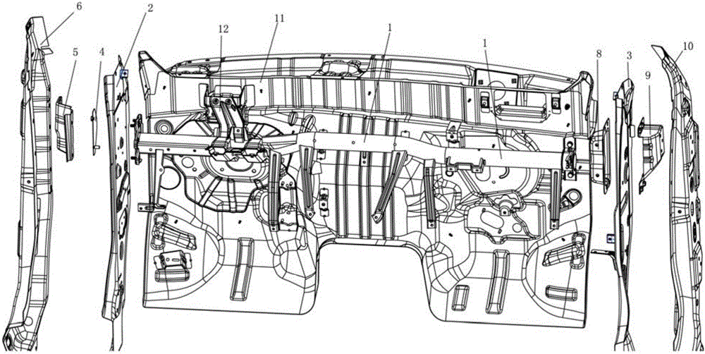
[0030] The following with attached Figure 2 to Figure 7 The instrument panel beam mounting assembly of the present invention will be further described in detail.

[0031] Instrument panel beam mounting assembly of the present invention, please refer to Figure 2 to Figure 7 , including a left mounting assembly for installing the instrument panel beam 1 on the left front side panel welding assembly 2 and a right mounting assembly for installing the instrument panel beam 1 on the right front side panel welding assembly 3, the right mounting assembly includes The U-shaped crossbeam right mounting bracket 8 with flanging on both sides and the U-shaped reinforcing plate 9 with flanging on both sides arranged between the welding assembly 3 of the right front side plate and the inner panel 10 on the right side, The crossbeam right mounting bracket 8 is fixed to the instrument panel crossbeam 1 in the X direction, and the two sides of the right front side panel welding assembly 3 ar...


PUM


Abstract

The invention discloses a gauge board beam installation component which consists of a left installation component used to install the gauge board beam to the weld assembly of the left front side plate, and a right installation component used to install the gauge board beam to the weld assembly of the right front side plate. The right installation component comprises a U-shape right mounting bracket of the beam with flanged edges on both sides and a U-shape reinforcing plate with flanged edges on both sides set between the weld assembly of the right front side plate and the right internal plate. The right mounting bracket of the beam is fixed with the gauge board beam along X direction. Both sides of the weld assembly of the right front side plate are respectively fixed with the right mounting bracket of the beam and the U-shape reinforcing plate. The other side of the U-shape reinforcing plate is fixed with the right internal plate. The gauge board beam installation component has a simple structure and can be installed conveniently. Besides, the installation component also has enough rigidity and a high mode, and can prevent the steering wheel and gauge board from shaking at a low speed.

Description

technical field [0001] The present invention relates to mounting assemblies, in particular to instrument panel beam mounting assemblies. Background technique [0002] In the existing body-in-white structure, the instrument panel beam is the mounting bracket for the instrument panel components of the vehicle. Insufficient installation stiffness modality may easily cause the vibration of the steering wheel and the instrument panel, which directly affects the user's use and perception. [0003] 1. The instrument panel beam is only installed on the left and right front side panels (such as figure 1 As shown), the support force and limit of the instrument panel beam are provided through the left and right front side panels and reinforcement plates (generally the front side panel is 0.8mm, the reinforcement plate is 1.2mm, and the total thickness is about 2.0mm); the rigidity of the instrument panel beam is insufficient. Steering wheel and dashboard vibrate at lower speeds. [0...

Claims


Application Information

Patent Timeline
Patent Type & Authority Applications(China)
IPC IPC(8): B62D25/14
Inventor 周远辉陈超福王晓蒙肖春燕彭斌
Owner SAIC-GM-WULING AUTOMOBILE CO LTD
Why Eureka
Try Eureka