Driving shaft assembly with support structure

A technology for driving shafts and bearing retaining rings, which is applied in the directions of axles, wheels, transportation and packaging, etc. It can solve the problems that the vibration and modal frequency of the driving shaft cannot be optimized, cannot be adjusted, and the fit is loose, etc., and the structure is simple , Strong practicability, the effect of reducing vibration

Inactive Publication Date: 2014-02-26
BEIJING CHANGAN AUTOMOBILE ENG TECH RES
View PDF4 Cites 3 Cited by
  • Summary
  • Abstract
  • Description
  • Claims
  • Application Information

AI Technical Summary

Problems solved by technology

When the dimensional tolerance of the outer ring of the bearing goes down and the dimensional tolerance of the inner ring of the bracket goes up, the fit clearance between the outer ring 21 of the bearing and the inner ring 11 of the bracket is the largest. Among them, the vibration and modal frequency of the drive shaft cannot be optimized, and cannot be adjusted. If it is improved, the bracket assembly with higher tolerance accuracy can only be replaced, resulting in waste

Method used


Image

  • Driving shaft assembly with support structure
  • Driving shaft assembly with support structure
  • Driving shaft assembly with support structure

Examples


Embodiment Construction

[0012] Further illustrate structure of the present invention below in conjunction with accompanying drawing:

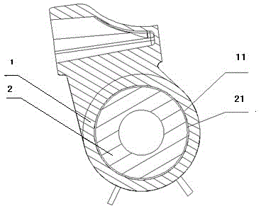
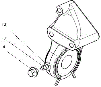
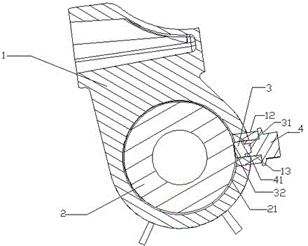
[0013] see figure 2 with image 3 , The drive shaft assembly with a bracket structure includes a bracket body 1, a bearing retaining ring and a spring assembly 2, a rubber plug 3 and a hollow bolt 4. When casting the drive shaft bracket body 1, cast a machinable boss 12 as required, tap the threaded through hole 13 of the corresponding specification along the radial direction of the bracket body on the boss, make the hollow bolt 4 that matches the threaded through hole, and Install the glue plug 3 in the groove 41 of the hollow bolt 4, after the tail part 31 of the glue plug and the groove 41 of the hollow bolt 4 are assembled through interference fit, screw the hollow bolt 4 into the threaded through hole 13 on the boss 12 , the rubber plug 3 and the threaded hole 13 of the boss are an interference fit. At this time, the end 32 of the rubber plug presses the outer...


PUM


Abstract

The invention discloses a driving shaft assembly with a support structure. The driving shaft assembly comprises a support body 1 and a bearing retainer ring clamp spring assembly 2, a bearing outer ring 21 of the bearing retainer ring clamp spring assembly 2 is installed in a support inner ring 11 of the support body 1, and the bearing outer ring 21 is in clearance fit with the support inner ring 11. The driving shaft assembly is characterized in that a threaded through hole is formed in the radial direction of the support body 1, a rubber plug 3 is installed in the threaded through hole, an end portion 32 of the rubber plug presses the bearing outer ring 21 tightly, a bolt 4 is screwed into the threaded through hole, the rubber plug 3 is pressed tightly, the pressing force to the bearing outer ring is generated through compression of the rubber plug 3, and therefore the matched tightness degree between the bearing outer ring 21 and the support inner ring 11 is adjusted so as to achieve the purposes of vibration reducing and mode optimization. The driving shaft assembly has the advantages of being simple in structure, convenient to operate, high in practicability and the like.

Description

technical field [0001] The invention belongs to automobile parts, in particular to the drive shaft assembly structure of the automobile. Background technique [0002] At present, the drive shaft assembly with bracket structure on the car is generally not connected to or provided with components other than the support drive shaft. See figure 1 , its structure includes a bracket body 1, a bearing retaining ring and a snap ring assembly 2. In this structure, the bearing retaining ring and the bearing outer ring 21 of the snap ring assembly 2 and the bracket inner ring 11 of the bracket body 1 generally fit with a small gap. When the dimensional tolerance of the outer ring of the bearing goes down and the dimensional tolerance of the inner ring of the bracket goes up, the fit clearance between the outer ring 21 of the bearing and the inner ring 11 of the bracket is the largest. Among them, the vibration and modal frequency of the drive shaft cannot be optimized and cannot be a...

Claims


Application Information

Patent Timeline
Patent Type & Authority Applications(China)
IPC IPC(8): B60B35/14B60B35/00
Inventor 唐建才张海成段龙彪
Owner BEIJING CHANGAN AUTOMOBILE ENG TECH RES
Why Eureka
Try Eureka