Rotation quenching clamp

A technology of rotating quenching and clamp head, which is applied in the field of quenching clamps, and can solve the problems of high probability of waste parts of precision workpieces, different quenching temperatures of quenched workpieces, etc.

Inactive Publication Date: 2014-06-11
DALIAN SHENGTE METAL NEW MATERIAL RES DEV
View PDF0 Cites 0 Cited by
  • Summary
  • Abstract
  • Description
  • Claims
  • Application Information

AI Technical Summary

Problems solved by technology

[0002] The current quenching process depends on the heating temperature required for different steels that are not quenched. For example, T8 steel requires a heating temperature of 800°C, which makes it very difficult to remove the workpiece after heating and quenching. Generally, the current quenching process is Throw the heated workpiece directly into the water, and the workpiece cannot extend into the bottom of the water, which will cause the quenching temperature of the quenched workpiece to be different. For some precision workpieces, this quenching method has a high probability of waste.

Method used


Image

  • Rotation quenching clamp
  • Rotation quenching clamp

Examples


Embodiment Construction

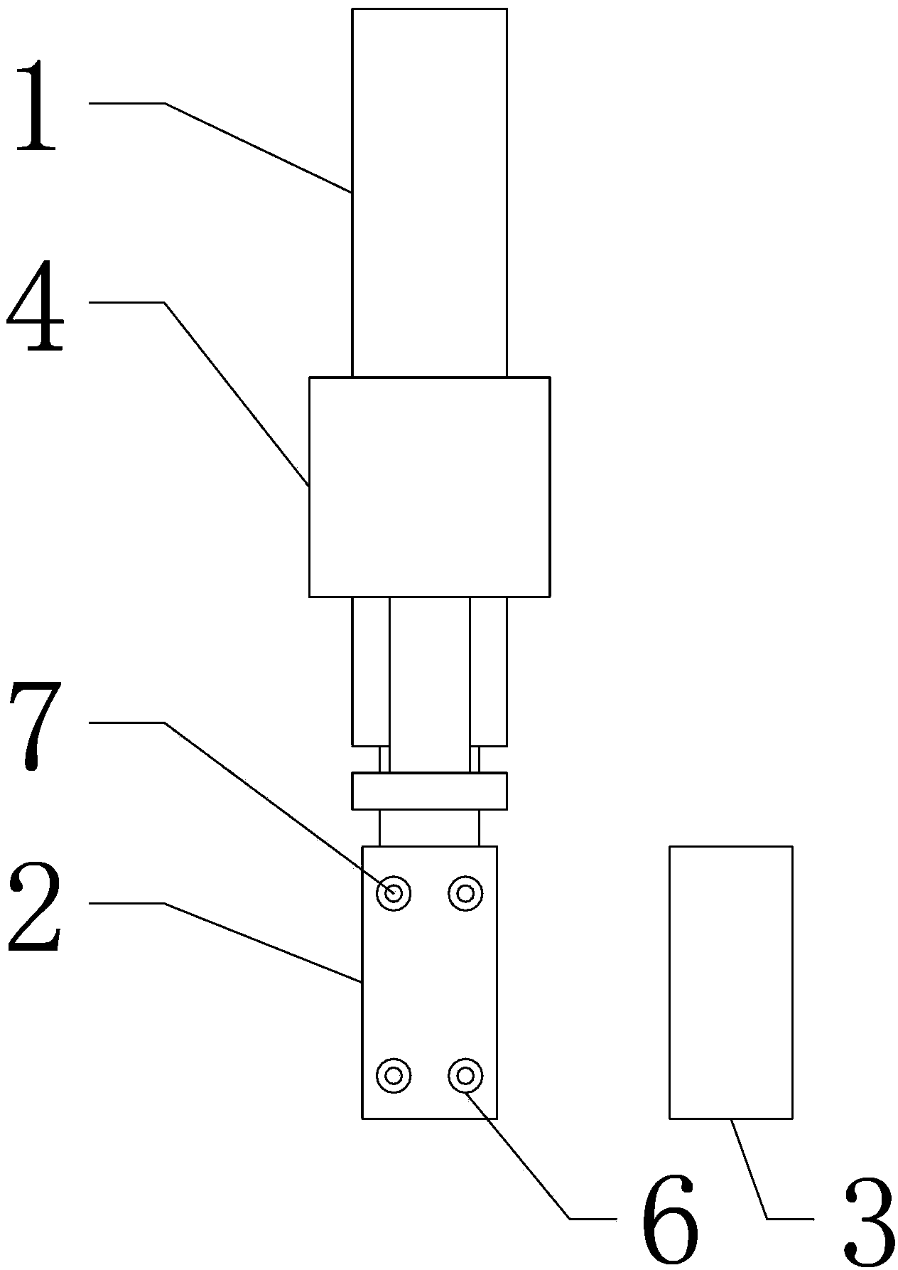
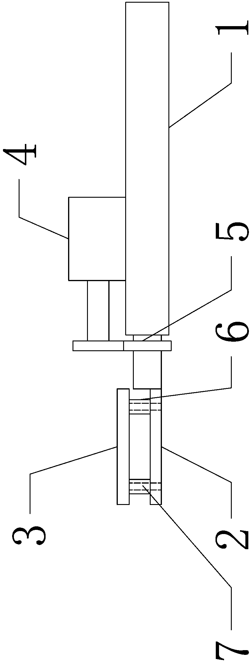
[0010] Such as figure 1 and figure 2 The rotary quenching pliers shown include: pliers arm 1, pliers head 2, auxiliary platen 3 and motor 4; Rotation; the rear end of the pliers head 2 is fixed with a drive gear 5, and the surface is provided with a magnet column 6; the motor 4 is fixed on the pliers arm 1, and the front output shaft gear sleeve is meshed with the drive gear 5 at the rear end of the pliers head 2; the auxiliary pressure plate 3 It has the same shape and size as the clamp head 2, and is adsorbed on the surface of the clamp head 2 by the magnet column 6; the clamp head 2 and the magnet column 6 are processed with a through hole 7 passing through the clamp head 2 and the magnet column 6;

[0011] The user of the present invention who has adopted the above-mentioned technical solution first absorbs the heated quenched workpiece through the magnet column 6. If the quenched workpiece is a flat plate structure, the auxiliary pressure plate 3 needs to be adsorbed to...


PUM


Abstract

The invention discloses a rotation quenching clamp, which comprises a clamp arm, a clamp head, an auxiliary pressure plate and a motor; the clamp head is fixed at the front end of the clamp arm through a rotating shaft at the axial direction, so that the clamp head can rotate by winding the shaft of the clamp arm; a driving wheel is fixed at the rear end of the clamp head, and a magnet column is provided on the surface; the motor is fixed on the clamp arm, and an output shaft tooth sleeve at the front end is engaged with the driving wheel at the rear end of the clamp head; according to the above technical scheme, the users can absorb the heated quenching workpiece by the magnet column, if the quenching workpiece is in a flat structure, the auxiliary pressure plate is required for absorbing to clamp the quenching workpiece, then the motor starts to work, the motor is driven by the tooth sleeve on the output shaft, the driving wheel is provided at the rear end of the clamp head, furthermore, the clamp head drives the clamping workpiece to rotate, then the clamping workpiece is stretched into water, the workpiece with a rotation state enables full quenching, and enables water mixing in a pool during the quenching engineering, so that the temperature unification can be reached.

Description

technical field [0001] The invention relates to a quenching tong, in particular to a quenching tong capable of driving a quenched workpiece to rotate. Background technique [0002] The current quenching process depends on the heating temperature required for different steels that are not quenched. For example, T8 steel requires a heating temperature of 800°C, which makes it very difficult to remove the workpiece after heating and quenching. Generally, the current quenching process is Throw the heated workpiece directly into the water, and the workpiece cannot reach the bottom of the water, which will cause different quenching temperatures on the upper and lower parts of the quenched workpiece. For some precision workpieces, this quenching method has a high probability of waste. Contents of the invention [0003] The technical problem to be solved by the present invention is to provide a quenching pliers capable of driving a quenched workpiece to rotate. [0004] In order ...

Claims


Application Information

Patent Timeline
IPC IPC(8): C21D1/18
Inventor 田绍洁
Owner DALIAN SHENGTE METAL NEW MATERIAL RES DEV
Why Eureka
Try Eureka