Refrigerator drawer and refrigerator applying same

A drawer and refrigerator technology, applied in applications, household appliances, household refrigeration devices, etc., can solve the problem of inconvenience in taking things, achieve smooth and labor-saving automatic flipping, good product experience, and reduce noise.

Inactive Publication Date: 2014-06-11
HISENSE(SHANDONG)REFRIGERATOR CO LTD
6 Cites 26 Cited by

AI-Extracted Technical Summary

Problems solved by technology

In the traditional drawer with a cover, a cover is set on the drawer, and the cover is slidingly connected with the drawer or connected with a rotating ...

Method used

As shown in Figure 2 and Figure 3, cover plate 200 can be a whole plate, but in order to reduce weight, provide user with better use effect, in the present embodiment, cover plate 200 is made of outer cover plate 210 and The inner cover plate 220 is composed of the outer cover plate 210 and the inner cover plate 220 which are locked and fixed by hooks 270. After the two are fixed, a gap is formed in the middle. Because the middle part of the cover plate 200 is hollow, the weight is reduced. When the drawer 100 is pushed and pulled, the friction caused by the gravity of the raised structure 230 is reduced, the cover plate 200 can be rotated more easily, and the sliding noise is effectively reduced.
Cover plate 200 is arranged on drawer 100 tops, and cover plate 200 is used to cover the drawer opening 500 of drawer 100, makes the food in drawer body 120 have relatively closed storage environment, and can open, conveniently take and put food.
One end of protruding structure 230 is provided with noise-reducing lubricating device, and noise-reducing lubricating device has lubricating or noise-reducing function, and in the present embodiment, preferably hard PVC cover 231 of noise-reducing device, hard PVC cover 231 surface The smoothness is high, which can reduce resistance. When the protruding structure 230 slides on the sliding surface 121 and the inner concave portion 122, the frictional force is reduced, making the push and pull of the drawer 100 and the rotation of the flip cover 200 easier. Since the rigid PVC sleeve 231 has a better effect of shock absorption and noise absorption, when the raised structure 230 slides, the noise can be reduced.
[0043] In order to make the opening angle of the cover plate 200 larger, the protruding structure 230 is arranged as an arc structure, and bends toward the rear end of the cover plate 200 to form an arc structure. The protruding structure 230 is set as an arc structure to increase the opening angle of the cover plate 200. If the protruding structure 230 is in a straight line shape, in order to ensure that the cover plate 200 is horizontal when closed, the depth of the corresponding inner concave portion 122 also needs to be increased. Larger, this will cause the sliding surface 121 slope to be too steep, and it is not easy ...

Abstract

The invention relates to a refrigerator drawer and a refrigerator applying the drawer. The drawer comprises a cover plate used for covering an opening of the drawer; a rotating shaft is fixed along the transverse direction of the rear side of the cover plate; the two ends of the rotating shaft are respectively arranged on the walls of inner liners at the two sides of the refrigerator; the drawer also comprises a support device used for opening or closing the cover plate; when the drawer is pushed or pulled, the support device enables the cover plate to overturn by the rotating shaft. The refrigerator drawer is simple in structure, can be automatically opened once being pulled out, has a humanization design, and is practical, convenient and low in noise.

Application Domain

Technology Topic

Image

  • Refrigerator drawer and refrigerator applying same
  • Refrigerator drawer and refrigerator applying same
  • Refrigerator drawer and refrigerator applying same

Examples

  • Experimental program(3)

Example Embodiment

[0035] Example 1
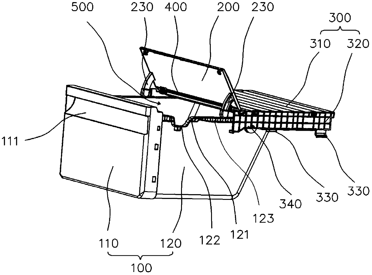
[0036] Such as figure 1 As shown, the cover 200 is in the shape of a rectangular parallelepiped, and a rotating shaft 400 is transversely provided on the rear side of the cover 200. The rotating shaft 400 can rotate freely on its axis. The two ends of the rotating shaft 400 are movably connected with the inner walls on both sides. The cover plate 200 is fixedly connected to the rotating shaft 400. The rotating shaft 400 rotates freely to drive the cover plate 200 fixed with it to flip, reaching the cover plate 200. The purpose of opening or closing. The rotating shaft 400 can also be in the form of a fixed rod that does not rotate by itself. The two ends of the rotating shaft 400 are fixedly connected with the inner walls on both sides, the cover plate 200 is movably connected with the rotating shaft 400, and the cover plate 200 is turned over with the rotating shaft 400 as the axis to reach the cover plate 200. The purpose of opening or closing. In order to make the cover 200 easier to turn over, the former connection structure is preferred in this embodiment.
[0037] The drawer 100 is slidably fitted with a sliding groove (not shown) fixed on the inner rib of the refrigerator, and can be pushed and pulled back and forth.
[0038] The supporting device is used to open or close the cover 200. In this embodiment, the supporting device includes a convex structure 230 provided on the lower end surface of the cover 200 facing the drawer body 120 and a convex structure 230 provided on the drawer 100. The sliding surface 121 on which the end of the structure 230 slides.
[0039] A raised structure 230 is provided on the left and right ends of the cover 200 facing the drawer body 120, and the position is close to the front end. Flanges 123 are provided on the left and right sides of the drawer body 120. The upper surface of the flanging 123 is a sliding surface 121, A predetermined position of the sliding surface 121 is provided with an inner concave portion 122 matching the convex structure 230. The height of the convex structure 230 matches the depth of the inner concave portion 122, and the end of the convex structure 230 can be on the sliding surface 121 slide.
[0040] When the drawer 100 is pushed into the refrigerator box, the end of the protruding structure 230 slides on the sliding surface 121, and finally slides into the inner recess 122. During the sliding process, the vertical height of the front end of the cover 200 gradually decreases. And by rotating the shaft 400, the cover 200 is closed. When the drawer 100 is pulled out, the protruding structure 230 slides out from the inner recess 122. In the process of sliding out, the vertical height of the front end of the cover 200 increases, and is rotated by the shaft 400 to realize the opening of the cover 200 .
[0041] In order to enable the convex structure 230 to slide into or out of the inner concave portion 122 smoothly and smoothly, during use, the concave portion 122 is slid in and out of the convex structure 230 to save effort and not generate large impact and noise. The side slope is set gently.
[0042] Considering the height of the raised structure 230, the height of the raised structure 230 matches the depth of the inner recess 122, so that when the raised structure 230 is completely slid into the inner recess 122, the cover 200 can be flush with the drawer opening 500.
[0043] In order to increase the opening angle of the cover 200, the protruding structure 230 is arranged in an arc structure, and is bent toward the rear end of the cover 200 to form an arc structure. The protruding structure 230 is set in an arc structure to increase the opening angle of the cover 200. If the protruding structure 230 is in a linear shape, in order to ensure that the cover 200 is horizontal when the cover 200 is closed, the corresponding depth of the concave portion 122 also needs to be increased. Large, this will cause the sliding surface 121 to be too steep and difficult to push and pull the drawer 100; in order to better realize the invention and facilitate the sliding of the drawer 100, it is necessary to ensure a gentle slope, reduce the depth of the inner concave portion 122, and reduce the linear convexity. Increase the length of the structure 230. In this case, since the length of the protruding structure 230 becomes smaller, the opening angle will also become smaller, and the opening effect of the cover 200 is not good. The protruding structure 230 is arranged in an arc structure, and is bent to the rear end of the cover plate 200 to form an arc structure, which can effectively avoid the above-mentioned problems, make the slope of the sliding surface 121 gentle and the opening angle of the cover plate 200 larger.
[0044] The position of the inner recess 122 should be matched with the position of the convex structure 230 on the cover 200. Specifically, the distance between the inner concave portion 122 and the drawer door 110 is equal to the distance between the end of the convex structure 230 and the drawer door 110. The purpose of this setting is to ensure that when the convex structure 230 completely slides into the inner concave portion 122, the cover 200 After being closed, the drawer 100 can be completely pushed into the refrigerator, and the cover 200 can completely cover the drawer opening 500.

Example Embodiment

[0045] Example 2
[0046] The front and rear length of the cover 200 can be increased or decreased according to the situation. The rear part of the cover 200 can be fixed on the inner wall using a shelf (not shown) or the like to cover the drawer openings that are not covered behind the cover 200.
[0047] This embodiment gives a better solution, such as figure 1 As shown, a layer frame 300 is added. The layer frame 300 is composed of a flat plate 310 and side plates 320 on both sides, and is an integrated structure. The side plates 320 are fixed to the inner ribs (not shown) on the inner wall by buckles 330 , The shelf 300 is easy to install, no other fixing parts are required to fix it, and a sliding groove (not shown) for the drawer 100 to slide is provided on the shelf 300, and the drawer 100 is slidably connected to the shelf 300. A slide groove (not shown) of the drawer 100 is provided on the side plate 320, and a runner 340 is provided on the side plate 320. The flange 123 of the drawer body 120 is slidingly fitted with the slide groove, and the bottom of the flange 123 is erected on the The wheel 340 is in contact with the rotating wheel 340, so that the drawer 100 can be pushed back and forth.
[0048] A rotating shaft 400 is transversely provided on the rear side of the cover 200. The rotating shaft 400 can rotate freely on its axis. The two ends of the rotating shaft 400 are respectively movably connected to the side plates 320 on both sides. The cover plate 200 is fixedly connected to the rotating shaft 400. The rotating shaft 400 rotates freely to drive the cover plate 200 fixed to it to turn over. The purpose of opening or closing the plate 200. The rotating shaft 400 can also be in the form of a fixed rod that does not rotate by itself. The two ends of the rotating shaft 400 are respectively fixedly connected to the side plates 320 on both sides. The cover plate 200 is movably connected to the rotating shaft 400. The cover plate 200 is turned over with the rotating shaft 400 as the axis to reach the cover. The purpose of opening or closing the plate 200. In order to make the cover 200 easier to turn over, the former connection structure is preferred in this embodiment.
[0049] The front and rear length of the plate 310 is less than the front and rear length of the drawer opening 500. The sum of the front and rear lengths of the plate 310 and the front and rear lengths of the cover 200 shall be the same as the front and rear lengths of the drawer opening 500, or slightly larger. After the cover 200 is closed, the drawer The opening 500 can be completely covered.
[0050] Due to the structure of the shelf 300 and the shelf 300 itself and the liner wall are snap-fixed, the sliding groove of the drawer body 120 does not need to be fixed on the liner wall by screws, which greatly facilitates installation. The cover plate 200 is connected to the shelf 300 through the rotating shaft 400, which avoids the problem that the rotating shaft 400 is directly fixed to the wall of the inner tank, which affects the appearance. At the same time, the cover plate 200 and the layer shelf 300 form a modular whole, which is also convenient The assembly of the cover 200 and the refrigerator.
[0051] The opening or closing manner of the cover 200 in this embodiment is the same as that of the first embodiment.

Example Embodiment

[0052] Example 3
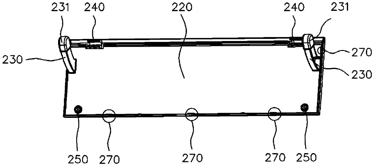
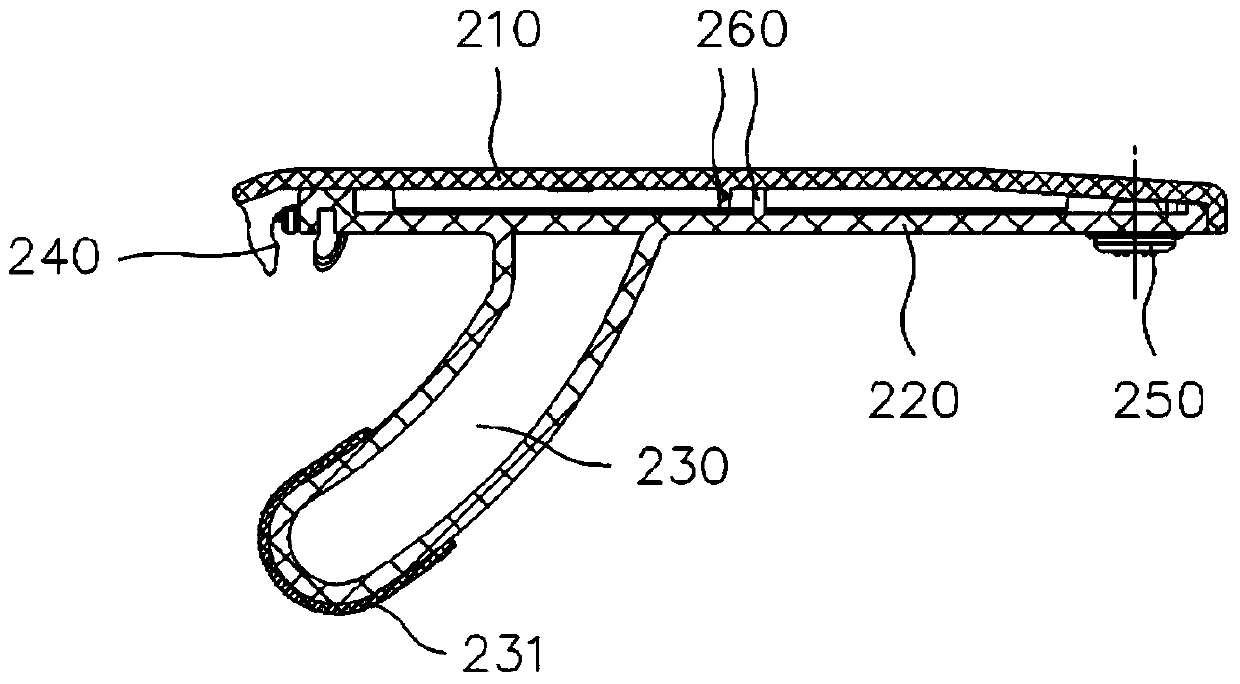
[0053] Such as figure 2 with image 3 As shown, the cover 200 can be a whole board, but in order to reduce weight and provide users with better use effects, in this embodiment, the cover 200 is composed of an outer cover 210 and an inner cover 220. The outer cover 210 and the inner cover 220 are clamped and fixed by a hook 270, and after the two are fixed, a gap is formed in the middle. Since the middle part of the cover 200 has a hollow structure, the weight is reduced. When the drawer 100 is pushed or pulled, the friction force of the convex structure 230 due to gravity is reduced, the cover 200 can be rotated more easily, and sliding noise is effectively reduced.
[0054] The outer cover 210 and the inner cover 220 are respectively provided with reinforcing ribs 260. After the two are fixed to form a gap, the reinforcing ribs 260 can provide support to prevent the flange from shrinking and deforming, and at the same time ensure the strength of the cover.
[0055] Two mounting seats 240 for mounting the rotating shaft 400 are provided on the inner cover 220. The rotating shaft 400 is fixedly installed on the mounting seat 240. The two ends of the rotating shaft 400 are movably connected to the inner wall or the shelf 300 on both sides. It can rotate freely, and the rotation of the shaft 400 drives the cover 200 to open or close.
[0056] A noise reduction lubrication device is provided at one end of the protrusion structure 230, and the noise reduction lubrication device has a lubrication or noise reduction function. In this embodiment, the noise reduction device is preferably a rigid PVC sleeve 231, which has a high surface finish. Resistance can be reduced. When the protruding structure 230 slides on the sliding surface 121 and the inner concave portion 122, the friction is reduced, which makes the push and pull of the drawer 100 and the rotation of the flip 200 easier. Since the rigid PVC sleeve 231 has a better shock absorption and noise absorption effect, the noise can be reduced when the protrusion structure 230 slides.
[0057] Two rubber damping pads 250 are provided on the inner cover 220. When the cover 200 is closed, the cover 200 will collide with the drawer 100, thereby generating noise. The rubber cushion 250 avoids the direct collision of the two hard materials of the cover 200 and the drawer 100, and reduces the noise during closing.

PUM

no PUM

Description & Claims & Application Information

We can also present the details of the Description, Claims and Application information to help users get a comprehensive understanding of the technical details of the patent, such as background art, summary of invention, brief description of drawings, description of embodiments, and other original content. On the other hand, users can also determine the specific scope of protection of the technology through the list of claims; as well as understand the changes in the life cycle of the technology with the presentation of the patent timeline. Login to view more.

Similar technology patents

Thermal Solution for Prismatic Lithium Ion Battery Pack

ActiveUS20130115506A1Reduce weightCell temperature controlLithium polymer cellThermal solution
Owner:NEOGRAF SOLUTIONS LLC

Glass film laminate

Owner:NIPPON ELECTRIC GLASS CO LTD

Classification and recommendation of technical efficacy words

Why Eureka
Try Eureka