Fluid heat exchange device

A heat exchange device and fluid technology, applied in the direction of instruments, electrical digital data processing, digital data processing components, etc., can solve problems such as bubble blockage, and achieve the effect of reducing the burden on the pump

Active Publication Date: 2014-06-11
ACER INC
View PDF5 Cites 0 Cited by
  • Summary
  • Abstract
  • Description
  • Claims
  • Application Information

AI Technical Summary

Problems solved by technology

[0004] The invention provides a fluid heat exchange device, which can solve the problem of air bubble clogging and improve the efficiency of fluid flowing in it

Method used


Image

  • Fluid heat exchange device
  • Fluid heat exchange device
  • Fluid heat exchange device

Examples


Embodiment Construction

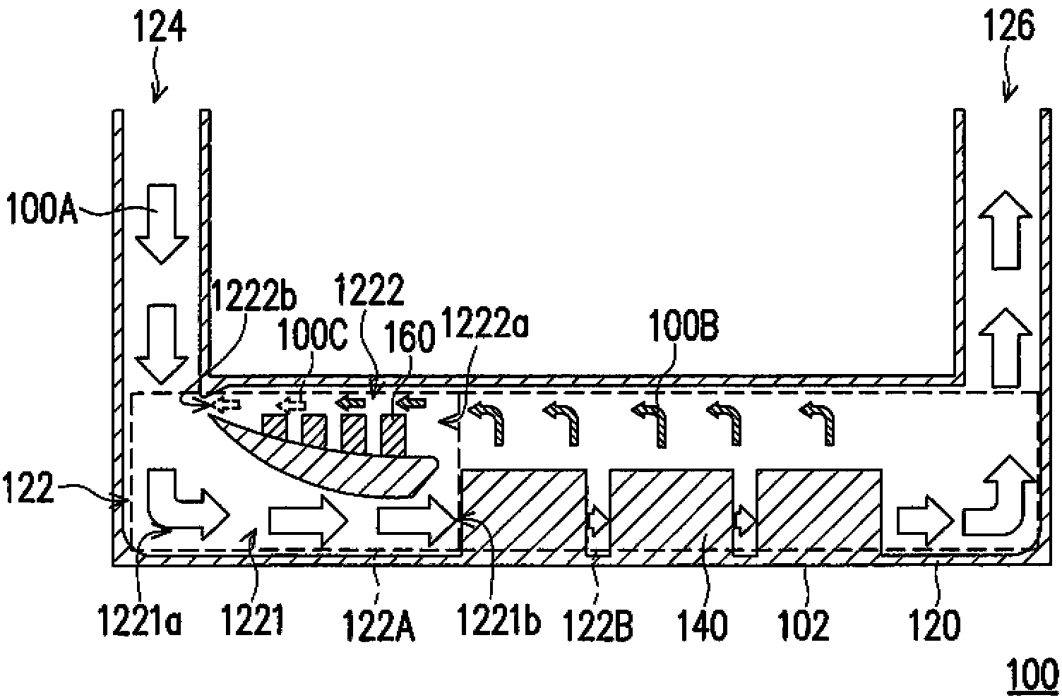
[0035] figure 1 It is a schematic cross-sectional view of a fluid heat exchange device according to an embodiment of the present invention. Please refer to figure 1 , The fluid heat exchange device 100 includes a housing 120 , a heat dissipation element 140 and a heat absorption element 160 . The housing 120 has a chamber 122 , an inlet line 124 and an outlet line 126 . The inlet pipeline 124 and the outlet pipeline 126 are respectively located on two sides of the chamber 122 , and the chamber 122 is communicated between the inlet pipeline 124 and the outlet pipeline 126 . In this embodiment, the chamber 122 can be divided into a first chamber 122A and a second chamber 122B which are communicated, wherein the inlet pipeline 124 is connected to the first chamber 122A, and the outlet pipeline 126 is connected to the second chamber 122B. connected. In this embodiment, the fluid heat exchange device 100 can be used in a server, for example, and the bottom 102 of the fluid heat...


PUM


Abstract

The invention provides a fluid heat exchange device, which comprises a shell and radiating elements, wherein the shell is provided with a chamber, an inlet pipeline and an outlet pipeline; the chamber comprises a first flow passage with a first inlet and a first outlet and a second flow passage with a second inlet and a second outlet; the sectional area of the first flow passage is gradually reduced from the first inlet to the first outlet; the sectional area of the second flow passage is gradually reduced from the second inlet to the second outlet; the radiating elements are positioned between the first outlet and the outlet pipeline; first fluid flows to the outlet pipeline from the inlet pipeline through the first flow passage and the radiating elements; a part of the first fluid flowing through the radiating elements absorbs heat to form a plurality of bubbles, the bubbles move into the second flow passage, and form second fluid, and the second fluid is converged into the first flow passage after flowing out of the second outlet.

Description

technical field [0001] The present invention relates to a heat exchange device, and in particular to a fluid heat exchange device. Background technique [0002] The server is the core computer that serves each computer in the network system. It can provide functions such as disk and printing services required by network users, and it can also be used by various clients to share various resources in the network environment with each other. The basic structure of the server is roughly the same as that of a general personal computer. It is composed of a central processing unit (CPU), a memory (Memory) and an input / output (I / O) device, and is internally connected by a bus (Bus). Connected, the central processing unit and the memory are connected through the North Bridge chip, and the input / output devices are connected through the South Bridge chip. [0003] Large-scale computer equipment such as servers will generate a lot of heat energy during operation, so how to effectively ...

Claims


Application Information

Patent Timeline
Patent Type & Authority Applications(China)
IPC IPC(8): G06F1/20
Inventor 谢铮玟廖文能
Owner ACER INC
Why Eureka
Try Eureka