
management system

A technology for management systems and electronic components, applied in the field of management systems, can solve problems such as insufficient information analysis and insufficient information, and achieve high-precision effects

Active Publication Date: 2019-03-12
JUKI CORP
View PDF7 Cites 0 Cited by
  • Summary
  • Abstract
  • Description
  • Claims
  • Application Information

AI Technical Summary

Problems solved by technology

However, if only the captured image is analyzed, the information for managing the mounting of electronic components may be insufficient or the analysis may be insufficient.

Method used


Image

  • management system
  • management system
  • management system

Examples


Embodiment Construction

[0038] Next, a mode (hereinafter referred to as embodiment) for implementing the management system according to the present invention will be described. In addition, the scope of the present invention is not limited by the following embodiments. In addition, the constituent elements in the following embodiments include elements within the so-called equivalent range, such as elements that can be easily conceived by those skilled in the art, substantially the same elements, and the like. In addition, components disclosed in the following embodiments may be appropriately combined.

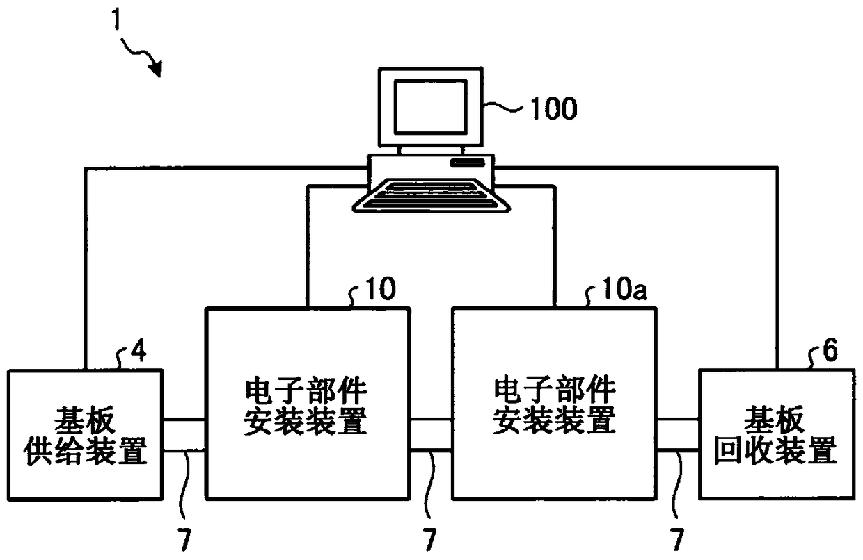
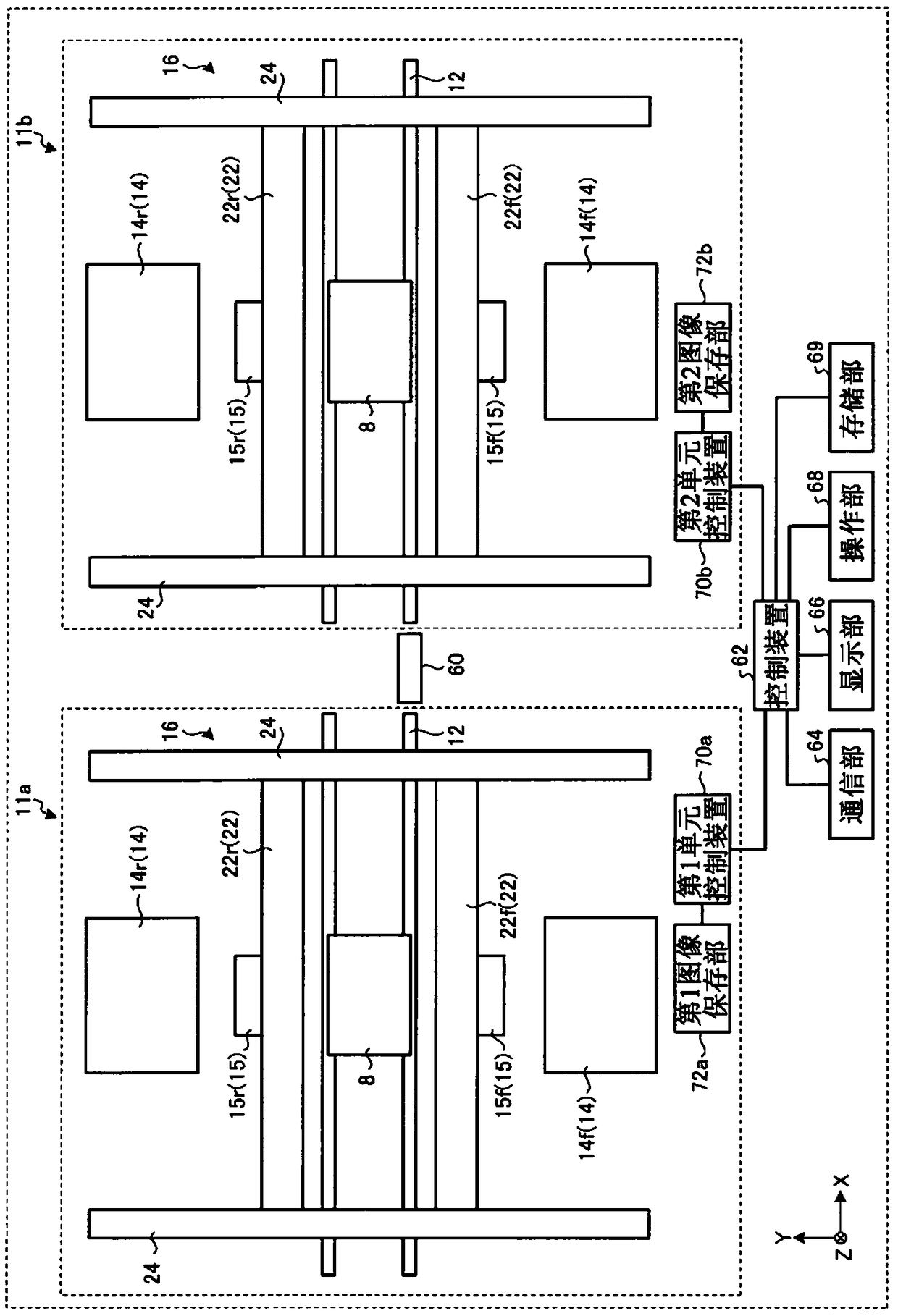
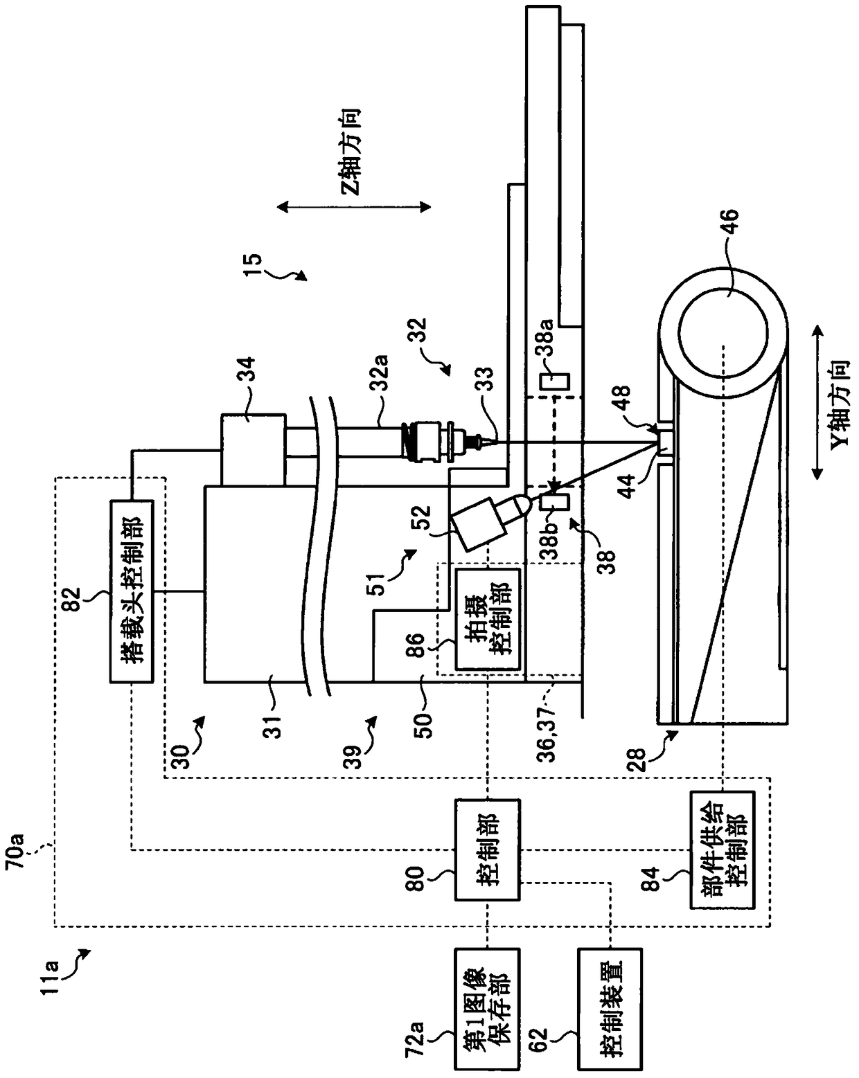
[0039] Hereinafter, a component mounting system as an embodiment of the present invention will be described in detail with reference to the drawings. figure 1 is a schematic diagram showing a schematic configuration of the component mounting system 1 . also, figure 1 The illustrated component mounting system 1 mounts components on boards and manages the boards on which the components are mounted. ...


PUM


Abstract

The present invention provides a management system capable of managing produced substrates with higher precision and with ease of understanding. The management system includes: at least one mounting head main body, which is moved by the mounting head moving mechanism; a substrate conveying unit, which conveys the substrate to the substrate conveying position reached by the mounting head main body; and a component supply unit, which supplies electronics. Components; a control device that controls the operation of the mounting head body and the component supply unit; a plurality of electronic component mounting units that mount electronic components on the substrate; a production history database that stores electronic components of the plurality of electronic component mounting units the history of the mounting operation of the electronic component; the display unit, which displays an image; and the control unit, which generates an image integrating the history of the electronic component mounting operation performed by the plurality of electronic component mounting units performed on the specified substrate, and displays it in the above-mentioned displayed on the display.

Description

technical field [0001] The present invention relates to a management system for managing the histories of components mounted on an electronic component mounting device. Background technique [0002] An electronic component mounting apparatus for mounting an electronic component on a substrate includes a mounting head having a suction nozzle, and the electronic component is held by the suction nozzle and mounted on the substrate. The electronic component mounting apparatus suctions the components located in the electronic component supply apparatus by moving the suction nozzle of the mounting head in the vertical direction. Then, the mounting head is relatively moved in a direction parallel to the surface of the substrate, and after reaching the mounting position of the adsorbed component, the suction nozzle of the mounting head is moved up and down to approach the substrate, so that the adsorbed electronic component mounted on the substrate. [0003] When electronic compon...

Claims


Application Information

Patent Timeline
Patent Type & Authority Patents(China)
IPC IPC(8): H05K13/00H05K13/04
CPCH05K1/0269H05K13/0408H05K13/0413H05K13/08
Inventor 松井谦阿部智贵千叶雄太高桥裕贵
Owner JUKI CORP
Learn More