Air conditioner bottom casing and split type air conditioner indoor machine

An air conditioner, integrated technology, applied in the directions of heating and ventilation hoods/covers, noise suppression, etc., can solve the problems of blocking wind flow, uneven air outlet, affecting wind flow, etc., to achieve smooth flow and improve air outlet effect. , reduce the blocking effect

Inactive Publication Date: 2014-06-18
GREE ELECTRIC APPLIANCES INC OF ZHUHAI
6 Cites 4 Cited by

AI-Extracted Technical Summary

Problems solved by technology

[0003] Since the bottom shell and the volute tongue are two separate parts, after the volute tongue is installed on the bottom shell, there is an installation gap between the volute tongue and the bottom shell, and there are alternating high and low surfaces from the volute tongue to the bottom shell, which are not smooth, that is, the air outlet The upper end surface of the air conditioner is not smooth, when the wind flows through the upper ...

Abstract

The invention provides an air conditioner bottom casing. The air conditioner bottom casing comprises a bottom casing body and a volute tongue which is arranged on an upper end surface of an air outlet of the bottom casing body; the volute tongue and the bottom casing body are in an integrated structure; the volute tongue and the bottom casing body are in smooth transition connection on an air outlet side. According to the air conditioner bottom casing, the volute tongue and the bottom casing body which are in the integrated structure are in smooth transition connection on the air outlet side, namely, no clearance or high-low alternating surface exists from the volute tongue to the bottom casing body, the upper end surface of the air outlet is smooth, blocking of air is reduced, air can flow out stably, influence to air flow is reduced, and accordingly the air outlet effect of the air conditioner is improved. The invention also provides a split type air conditioner indoor machine which is provided with the air conditioner bottom casing.

Application Domain

Technology Topic

Image

  • Air conditioner bottom casing and split type air conditioner indoor machine
  • Air conditioner bottom casing and split type air conditioner indoor machine
  • Air conditioner bottom casing and split type air conditioner indoor machine

Examples

  • Experimental program(1)

Example Embodiment

[0026] The embodiment of the present invention provides an air conditioner bottom case, which reduces the influence on the air flow and improves the air outlet effect of the air conditioner.
[0027] The technical solutions in the embodiments of the present invention will be clearly and completely described below with reference to the accompanying drawings in the embodiments of the present invention. Obviously, the described embodiments are only a part of the embodiments of the present invention, but not all of the embodiments. Based on the embodiments of the present invention, all other embodiments obtained by those of ordinary skill in the art without creative efforts shall fall within the protection scope of the present invention.
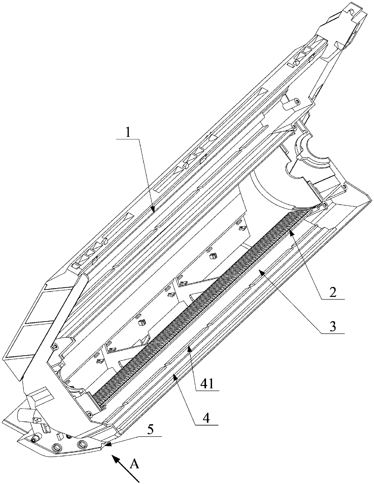
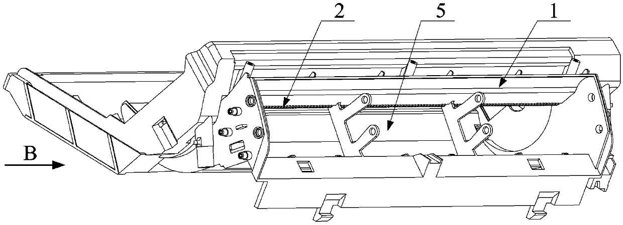
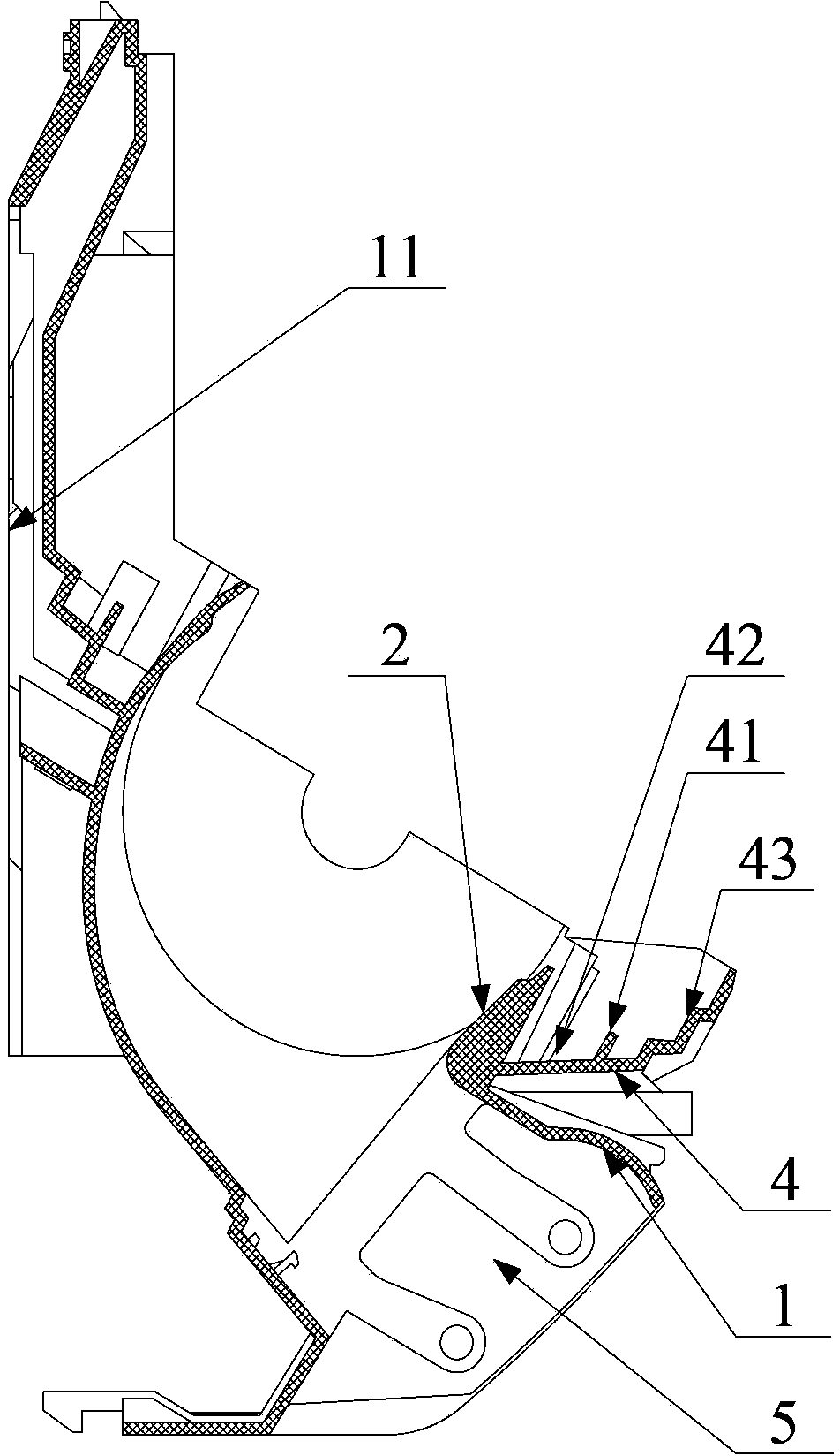
[0028] Please refer to the attached Figure 1-4 , figure 1 A schematic structural diagram of an air conditioner bottom case provided by an embodiment of the present invention; figure 2 for figure 1 Schematic diagram of the A-direction structure; image 3 for figure 2 Schematic diagram of the B-direction structure; Figure 4 Another schematic structural diagram of the bottom case of the air conditioner provided by the embodiment of the present invention.
[0029] The bottom case of the air conditioner provided in the embodiment of the present invention includes a bottom case body 1 and a volute 2 disposed on the upper end surface of the air outlet 5 of the bottom case body 1; The volute tongue 2 and the bottom shell body 1 are smoothly connected on the air outlet side, such as Figure 2-4 shown. The air outlet side refers to the side of the volute tongue 2 and the bottom case body 1 close to the air outlet 5 .
[0030] In the bottom case of the air conditioner provided by the embodiment of the present invention, the volute tongue 2 and the bottom casing body 1 are integrally constructed, and the volute tongue 2 and the bottom casing body 1 are smoothly connected on the air outlet side, that is, from the volute tongue 2 to the bottom casing body 1. There is no gap and no alternating high and low surface, that is, the upper end surface of the air outlet 5 is relatively smooth, which reduces the blocking of the wind, so that the wind can flow more smoothly, thereby reducing the impact on the wind flow and improving the air outlet of the air conditioner. Effect.
[0031] At the same time, in the bottom case of the air conditioner provided by the embodiment of the present invention, the bottom case body 1 and the volute tongue 2 are set as an integral structure, so when assembling the split-type air conditioner inner unit, it is not necessary to assemble the bottom case body 1 and the volute tongue 2 again. Obviously, the assembly process is reduced, thereby improving the assembly efficiency of the air conditioner.
[0032] Preferably, in the bottom case of the air conditioner provided in the above embodiment, the surface of the volute tongue 2 close to the air outlet side and the surface of the bottom case body 1 close to the air outlet side, one of which is a plane, and the other surface is facing away from the air outlet side. A convex arc surface in the direction of , and the two are connected by a rounded transition. In order to increase the air outlet space, the surface of the volute tongue 2 close to the air outlet side is preferably selected as a plane surface, and the surface of the bottom shell body 1 close to the air outlet side is an arc surface that protrudes in the direction away from the air outlet side, such as image 3 shown. The surface of the volute tongue 2 close to the air outlet side can also be set as an arc surface protruding in the direction away from the air outlet side, and the surface of the bottom case body 1 close to the air outlet side is a plane. Of course, the surface of the volute tongue 2 close to the air outlet side and the surface of the bottom shell body 1 on the air outlet side can also be arc surfaces that protrude to the same side respectively, and the two arc surfaces are smoothly connected by rounded corners or planes. Specifically, the two arc surfaces respectively protrude in a direction away from the air outlet side, of course, may also protrude in a direction close to the air outlet side, which is not specifically limited in the embodiment of the present invention.
[0033] In order to effectively improve the air outlet effect of the air conditioner, in the bottom case of the air conditioner provided by the above embodiment, the surface of the volute tongue 2 close to the air outlet side and the surface of the bottom casing body 1 close to the air outlet side are planes respectively; the volute tongue 2 and the bottom The connection surface of the shell body 1 close to the air outlet side is a plane, and the surface of the volute tongue 2 close to the air outlet side, the surface of the bottom shell body 1 close to the air outlet side and the connecting surface are in the same plane, such as Figure 4 shown. In the prior art, the volute tongue is installed on the bottom case, and there are alternating high and low surfaces from the volute tongue to the bottom case. , on the air outlet side, from the volute tongue 2 to the shell body 1 is a plane, that is, the upper end face of the air outlet 5 is a plane, which reduces the blocking of the wind, so that the wind can flow smoothly, thereby reducing the impact on the wind flow, improving The air outlet effect of the air conditioner.
[0034] In the bottom case of the air conditioner provided by the above-mentioned embodiment, the volute tongue 2 and the bottom casing body 1 have an integral structure, and preferably the volute tongue 2 and the bottom casing body 1 are injection-molded, that is, the integral volute tongue 2 and the bottom casing body 1 are formed by injection molding. One-piece injection-molded structure.
[0035] In order to further improve the air outlet effect of the air conditioner, in the bottom case of the air conditioner provided by the above embodiment, the end of the volute tongue 2 facing the air outlet side is provided with a rounded corner, that is, the end of the volute tongue 2 close to the fan blade is provided with rounded corners, such as image 3 and 4 As shown in the figure, the wind flows more smoothly, thereby improving the air outlet effect; at the same time, the noise reduction effect of the volute tongue 2 is also enhanced.
[0036] In order to further optimize the above technical solution, the bottom case of the air conditioner provided in the above embodiment also includes a water receiving plate 4 forming a water receiving tray 3 with the volute tongue 2, and the water receiving plate 4, the volute tongue 2 and the bottom shell body 1 are integrated structure. In order to form the water receiving tray 3, the water receiving plate 4 is located between the volute tongue 2 and the bottom shell body 1, that is, the water receiving plate 4 is located on the side of the volute tongue 2 away from the fan, and the water receiving plate 4 is connected to the volute tongue 2, such as image 3 and Figure 4 As shown, specifically, the side wall of the volute tongue 2 away from the fan and the water receiving plate 4 form a water receiving tray 3 for receiving the condensed water on the evaporator. By designing the water receiving plate 4 , the volute tongue 2 and the bottom case body 1 into an integrated structure, the assembly process is further reduced, thereby further improving the assembly efficiency of the air conditioner.
[0037]The evaporator is arranged on the bottom shell of the air conditioner. In order to make the position of the evaporator more stable, preferably, in the bottom shell of the air conditioner provided by the above embodiment, the water receiving plate 4 includes: a water receiving part 42 and a water receiving part 42 The supporting part 43 is connected and used to support the evaporator of the air conditioner, wherein the water receiving part 42 is connected with the volute tongue 2 and forms the water receiving tray 3 . The evaporator is supported by the support portion 43 to further strengthen the evaporator. Generally, the support portion 43 is inclined in the direction away from the volute tongue 2 and is matched with the bottom end of the evaporator. In order to restrict the evaporator from sliding away from the supporting part 43, a baffle 41 for limiting the evaporator is provided on the side of the supporting part 43 close to the water receiving part 42, and the baffles 41 are distributed along the evaporator, so that the baffle 41 can block the evaporator , to prevent the evaporator from moving to the volute 2. In order to enable the condensed water on the evaporator to flow into the water receiving tray 3, it is preferable to select at least two baffles 41, and a gap is set between two adjacent baffles 41, such as figure 1 As shown, the condensed water flows into the water receiving pan 3 through the gap. Of course, the baffle 41 may also be one, and a plurality of through holes for the condensed water to pass through are provided on the baffle 41 , or the two ends of the baffle 41 and the bottom case body 1 have gaps for the condensed water to pass through. The specific structure of the baffle plate 41 is not specifically limited in the embodiment of the present invention.
[0038] Preferably, in the bottom case of the air conditioner provided in the above embodiment, the support parts 43 are distributed in a stepped shape, such as image 3 and Figure 4 As shown, the support portion 43 includes: a plurality of support plates and connecting plates connecting two adjacent support plates, wherein the support plates are distributed horizontally and sequentially from low to high, and the connecting plates are generally distributed along the vertical direction, In order to facilitate the support portion 43 to support the evaporator. Preferably, the connecting plate and the supporting plate are inclined. Specifically, the connecting plate is parallel to the side wall of the volute tongue 2 close to the water receiving plate 4 . Of course, the support portion 43 may also have other structures, as long as the support portion 43 can support the evaporator, and the embodiment of the present invention does not specifically limit the structure of the support portion 43 .
[0039] In order to facilitate the water receiving plate 3 formed by the water receiving plate 4 and the volute tongue 2 to receive water, in the bottom case of the air conditioner provided in the above embodiment, the water receiving portion 42 is perpendicular to the installation wall 11 of the bottom case body 1, so that the connection can be The water pan 3 can accommodate more condensed water, preventing the condensed water from flowing out of the water receiving pan 3 and into the room. The mounting wall 11 of the bottom case body 1 specifically refers to the side wall of the bottom case body 1 in contact with the mounting wall. Generally, if the installation wall is a vertical plane, that is, the installation wall 11 of the bottom case body 1 is also a vertical plane, the water receiving parts 42 are distributed horizontally. Of course, the water receiving portion 42 can also be distributed in other directions, as long as the water receiving plate 4 and the volute tongue 2 can form the water receiving plate 3 .
[0040] Based on the air conditioner bottom case provided by the above embodiments, an embodiment of the present invention further provides a split-type air conditioner internal unit, where the split type air conditioner internal unit includes the air conditioner bottom case described in the above embodiments.
[0041] Since the split-type air conditioner indoor unit provided by the embodiment of the present invention has the air conditioner bottom case provided in the above-mentioned embodiment, and the air conditioner bottom case has the above-mentioned technical effects, the split-type air conditioner internal unit provided by the embodiment of the present invention also has corresponding The technical effect will not be repeated in this article.
[0042] The above description of the disclosed embodiments enables any person skilled in the art to make or use the present invention. Various modifications to these embodiments will be readily apparent to those skilled in the art, and the generic principles defined herein may be implemented in other embodiments without departing from the spirit or scope of the invention. Thus, the present invention is not intended to be limited to the embodiments shown herein, but is to be accorded the widest scope consistent with the principles and novel features disclosed herein.

PUM

no PUM

Description & Claims & Application Information

We can also present the details of the Description, Claims and Application information to help users get a comprehensive understanding of the technical details of the patent, such as background art, summary of invention, brief description of drawings, description of embodiments, and other original content. On the other hand, users can also determine the specific scope of protection of the technology through the list of claims; as well as understand the changes in the life cycle of the technology with the presentation of the patent timeline. Login to view more.

Similar technology patents

Blood purifier exhaust method

ActiveCN106215265AReduce blockingShorten exhaust timeOther blood circulation devicesMedical devicesAqueous solutionEngineering
Owner:JAFRON BIOMEDICAL

Heating device and radar housing

PendingCN111263473AReduce blockingReduce or even avoid blockingWave based measurement systemsHeater elementsPhysicsElectric heating
Owner:NINGBO SUNNY AUTOMOTIVE OPTECH

Discharging device

Owner:泉州臻美智能科技有限公司

Ceramic intelligent wearable equipment

PendingCN110190859AIncrease clearance areaReduce blockingDetails for portable computersTransmissionCommunication effectsMetallurgy
Owner:HUAQIN TECH CO LTD

Classification and recommendation of technical efficacy words

  • Reduce blocking
  • Smooth flow

Autonomous filter element

InactiveUS20100237013A1Improving filter life and performanceReduce blockingMembranesVolume/mass flow measurementMembrane configurationEngineering
Owner:MILLIPORE CORP

Angle adjustable vibration discharging device

InactiveCN107380768AReduce cloggingReduce blockingLarge containersPush pullEngineering
Owner:泉州臻美智能科技有限公司

Annular movement sieve

InactiveCN102179364AReduce blockingImprove production and screening efficiencySievingScreeningEngineeringSieve
Owner:张玉伟

LED headlamp

Owner:南宁燎旺车灯股份有限公司

Catheter with valve

Owner:MOZARC MEDICAL US LLC

Constructing method for fish shelter under stress of high silt concentration flood

InactiveCN106049347AImprove flow coefficientSmooth flowWater resource protectionBarrages/weirsRiver waterFish habitat
Owner:FRESHWATER FISHERIES RES INST OF SHANDONG PROVINCE
Why Eureka
Try Eureka