A modular three-way adjustable steel comb-shaped expansion device and its installation method

A three-way adjustment and expansion device technology, applied in bridge parts, bridges, buildings, etc., can solve the problems of lack of waterproof and decontamination measures, high construction requirements, shortened service life of steel plates, etc. The effect of high rigidity and strong impact resistance

Active Publication Date: 2015-11-18
CHANGSHA UNIVERSITY OF SCIENCE AND TECHNOLOGY
View PDF5 Cites 3 Cited by
  • Summary
  • Abstract
  • Description
  • Claims
  • Application Information

AI Technical Summary

Problems solved by technology

There are many types of bridge expansion devices, but because the existing bridge expansion devices cannot adapt to the lateral deflection and vertical displacement of the bridge structure, the actual use effect is not satisfactory
[0003] Due to the high construction requirements and asynchronous installation of ordinary steel comb-shaped telescopic devices on the market today, the flatness of the upper surface of the telescopic device and the transition section of the bridge deck is likely to be insufficient after installation, resulting in driving noise and driving impact during use. The increased driving force accelerates the wear of the steel plate and shortens the service life of the steel plate; the existing bridge expansion device itself lacks waterproof and decontamination measures, resulting in the accumulation of sundries under the comb plate. After rolling and compacting, it is difficult to achieve ideal decontamination, which seriously affects the free expansion and contraction of the comb teeth; the existing bridge expansion device cannot effectively adapt to the small deflection caused by the uneven lateral deformation of the bridge structure and the vertical deflection between the comb tooth plate structure. Altitude change caused by displacement

Method used


Image

  • A modular three-way adjustable steel comb-shaped expansion device and its installation method
  • A modular three-way adjustable steel comb-shaped expansion device and its installation method
  • A modular three-way adjustable steel comb-shaped expansion device and its installation method

Examples


Embodiment Construction

[0062] The specific implementation manners of the present invention will be further described in detail below in conjunction with the accompanying drawings and embodiments. The following examples are only used to illustrate the present invention, but can not be used to limit the scope of the present invention.

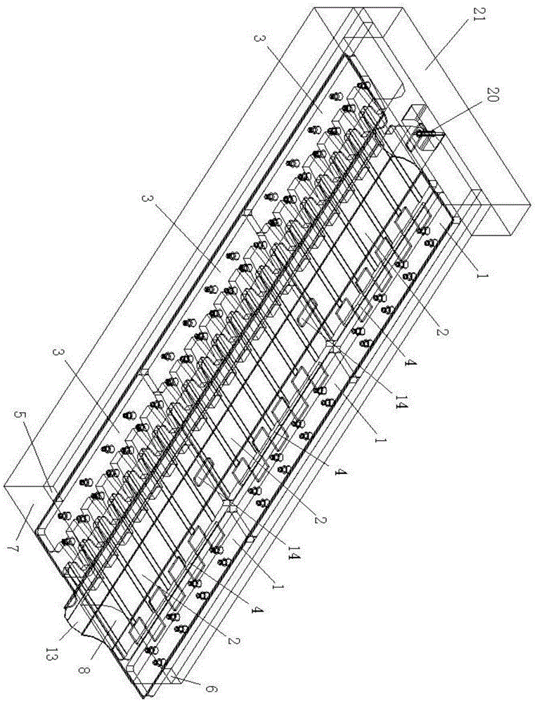
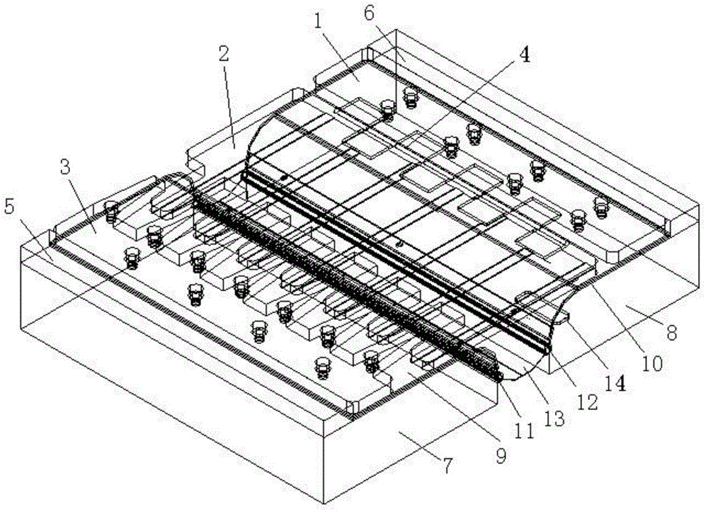
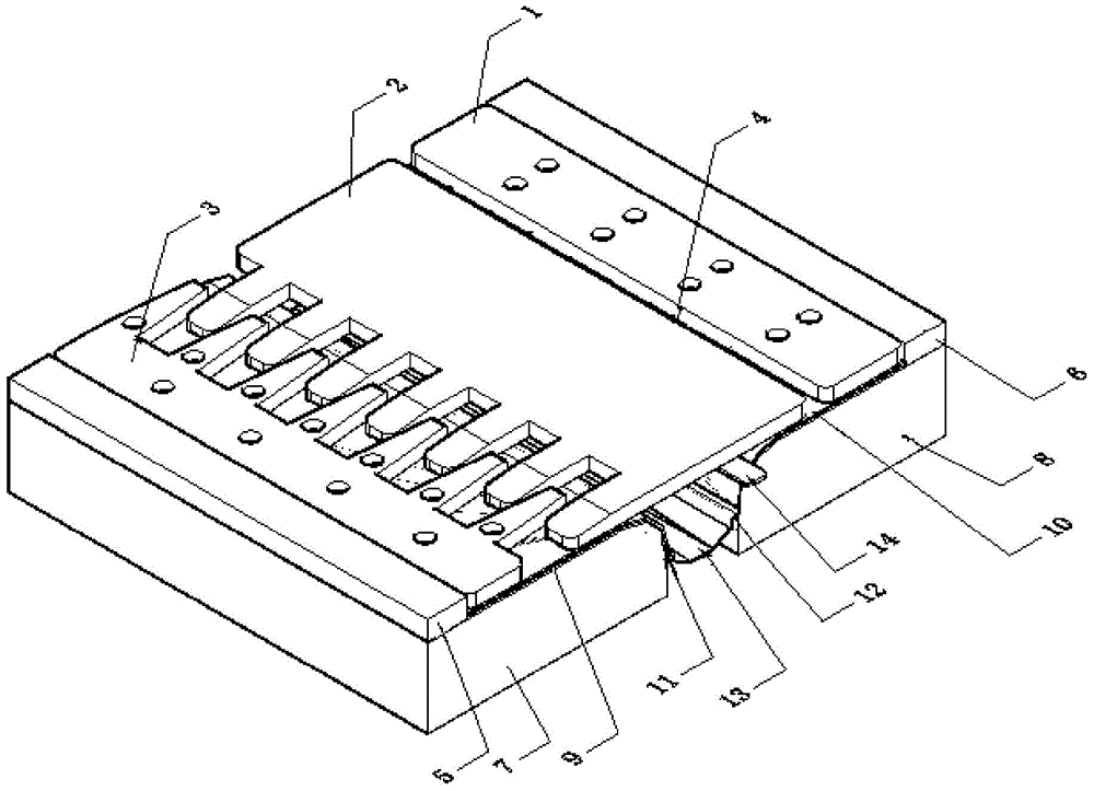
[0063] A modular three-way adjustable steel comb-shaped expansion device of the present invention is composed of multiple units with the same structure, and each unit includes: surface layer steel plate expansion module, transition section concrete I5, transition section concrete II6, anchorage area concrete Ⅰ7. Concrete in the anchorage area Ⅱ8, stainless steel sliding plate Ⅰ9, stainless steel sliding plate Ⅱ10, waterstop connector Ⅰ11, waterstop connector Ⅱ12, rubber waterstop 13; the surface steel plate telescopic module includes: steel plate anchor block Ⅰ1, steel plate Movable block 2, steel plate anchor block II3, steel plate connector 4, and steel plate fastene...


PUM


Abstract

The invention relates to the design field of devices needed for civil and traffic facilities, in particular to a modularized steel comb plate retractable device with a three-direction adjusting function and an installation method of the modularized steel comb plate retractable device. According to intrinsic design defects of a bridge retractable device, the modularized steel comb plate retractable device with the three-direction adjusting function and the installation method of the modularized steel comb plate retractable device are provided. Based on that all excellent properties of a common steel comb-shaped retractable device are kept, the function, which an existing retractable device does not have, of lateral deflection and vertical dislocation adjusting is added; contamination removal defects of the common steel comb-shaped retractable device are overcome, and a waterproof contamination removal device is added, which helps the device to be maintained; the installation process is simplified, and construction difficulty is reduced; the service life of the steel comb-shaped retractable device is prolonged, and the using efficiency of the bridge retractable device is brought into play to the maximum degree.

Description

technical field [0001] The invention relates to the design field of devices required in civil engineering and traffic facilities, in particular to a modularized three-way adjustable steel comb-shaped expansion device and an installation method thereof. Background technique [0002] The bridge telescopic device is a device embedded in the structural joints of the bridge to meet the needs of the deformation of the bridge deck and ensure that vehicles pass through the bridge deck smoothly. Its function is to enable the bridge structure to expand and contract freely under the effects of temperature changes, concrete shrinkage, creep, and vehicle loads, and to take into account the functions of waterproofing and decontamination. There are many types of bridge expansion devices, but the actual use effect is not satisfactory because the existing bridge expansion devices cannot adapt to the lateral deflection and vertical displacement of the bridge structure. [0003] Due to the hi...

Claims


Application Information

Patent Timeline
Patent Type & Authority Patents(China)
IPC IPC(8): E01D19/06
Inventor 田仲初易超蒋田勇彭文平彭涛谢海波
Owner CHANGSHA UNIVERSITY OF SCIENCE AND TECHNOLOGY
Why Eureka
Try Eureka