
Automatic adjusting device and adjusting method for eliminating induction log direct coupling signals

A technology of automatic adjustment and adjustment method, which is applied in the direction of electric/magnetic detection for well logging records, can solve problems such as difficult debugging, low precision, and poor stability, and achieve good stability, high precision, and elimination of direct coupling signal effect

Inactive Publication Date: 2014-06-25
UNIV OF ELECTRONIC SCI & TECH OF CHINA
View PDF7 Cites 10 Cited by
  • Summary
  • Abstract
  • Description
  • Claims
  • Application Information

AI Technical Summary

Problems solved by technology

The above method makes it unnecessary to directly change the coil in the process of eliminating the direct coupling signal, which simplifies the cancellation process, but it still needs to be done manually, which is difficult to debug and has the disadvantages of low precision and poor stability.

Method used


Image

  • Automatic adjusting device and adjusting method for eliminating induction log direct coupling signals
  • Automatic adjusting device and adjusting method for eliminating induction log direct coupling signals
  • Automatic adjusting device and adjusting method for eliminating induction log direct coupling signals

Examples


Embodiment Construction

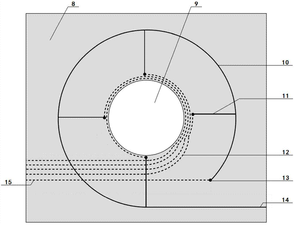
[0026] Step 1: Design and install the receiving coil system. Such as figure 1 As shown, the general logging tool adopts the method of connecting the compensation coil and the receiving coil in series, and uses the principle that the two coils are wound in opposite directions and the positive and negative signals of the direct coupling signal are opposite to achieve the purpose of canceling the direct coupling signal of the receiving coil system. As mentioned above, this coil structure has disadvantages such as poor consistency, difficult control of stability and precision, and complicated cancellation process. For this reason, the present invention proposes a method for designing a receiving coil system based on a multilayer PCB.

[0027] Specifically, on the basis of the receiving coil and compensation coil, an adjusting coil with adjustable turns based on multilayer PCB design is added. The structure of the entire receiving coil system is as follows: figure 2 shown. Amon...


PUM


Abstract

The invention discloses an automatic adjusting device and an adjusting method for eliminating induction log direct coupling signals, and relates to the field of direct coupling signal offset of receiving coils in induction log tools. The automatic adjusting device comprises a coil former, a transmitting coil, a base coil with fixed turns and an adjusting coil with adjustable turns. The adjusting coil is designed based on multi-layer PCBs, a plurality of taps are led out from the PCBs, different taps correspond to different coil turns, and all the taps are mutually connected to an analog switch and are then connected with a signal conditioning circuit, a sampling circuit and a main control circuit in sequence. In an automatic offset process, the main control circuit controls the analog switch to switch different taps of the adjusting coil, the direct coupling signal intensity of the current tap is calculated, and the analog switch is gated on the tap with the weakest direct coupling signal of the coil through a direct coupling offset algorithm, and the automatic direct coupling offset effect which is easy to achieve, precise and stable is finally achieved.

Description

technical field [0001] The invention belongs to the technical field of induction well logging, in particular to the field of cancellation of direct coupling signals of receiving coils in well logging instruments. Background technique [0002] The transmission signal of the transmission coil of the induction logging tool generates eddy current in the conductive formation, and the eddy current generates a secondary induction signal carrying formation information to the receiving coil, and the formation information is obtained by measuring the secondary induction signal. However, in the actual measurement process, due to the coupling effect between the transmitting coil and the receiving coil, the receiving coil will also receive the direct coupling signal from the transmitting coil. The direct-coupled signal does not carry formation information, and is generally more than an order of magnitude larger than the secondary induction signal, so the direct-coupled signal of the rece...

Claims


Application Information

Patent Timeline
IPC IPC(8): G01V3/28
Inventor 管国云汪浩聂在平孙向阳邱玉杰
Owner UNIV OF ELECTRONIC SCI & TECH OF CHINA
Learn More