Debugging method, debugger and system

A debugging method and a debugger technology, which are applied in transmission systems, heating and ventilation control systems, heating and ventilation safety systems, etc., can solve problems such as low efficiency, high cost, cumbersome debugging process, etc., to simplify the debugging process and reduce the cost of debugging cost, and the effect of improving debugging efficiency

Inactive Publication Date: 2017-04-19
GREE ELECTRIC APPLIANCES INC
View PDF5 Cites 11 Cited by
  • Summary
  • Abstract
  • Description
  • Claims
  • Application Information

AI Technical Summary

Problems solved by technology

[0006] The embodiment of the present invention provides a debugging method, a debugger and a system, which are used to solve the problems of cumbersome debugging process, low efficiency and high cost in the existing debugging method

Method used


Image

  • Debugging method, debugger and system
  • Debugging method, debugger and system
  • Debugging method, debugger and system

Examples


Embodiment 1

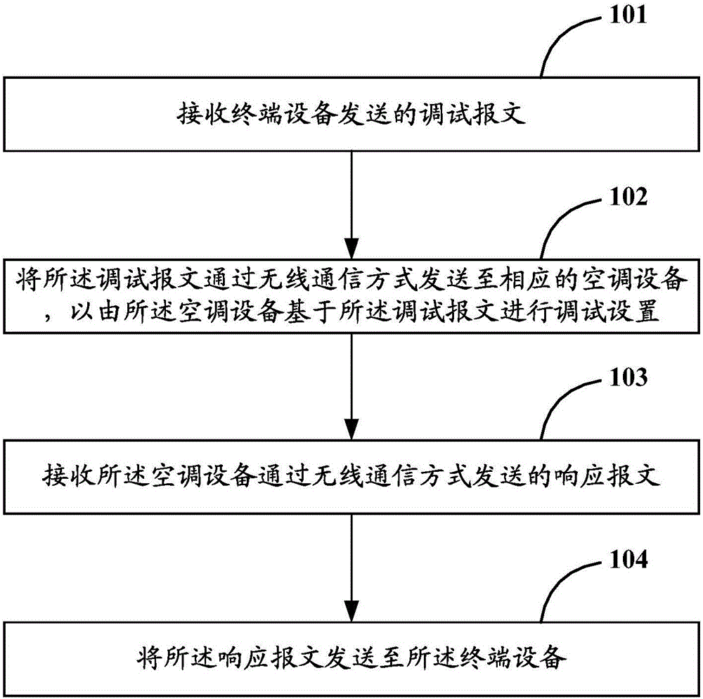
[0033] In order to solve the problems of cumbersome debugging process, low efficiency and high cost existing in the existing debugging method, the first embodiment of the present invention provides a debugging method, such as figure 1 As shown, it is a schematic flowchart of the debugging method described in Embodiment 1 of the present invention. Specifically, by figure 1 It can be seen that the debugging method may include the following steps:

[0034] Step 101: Receive a debugging message sent by a terminal device;

[0035] Step 102: Send the debugging message to a corresponding air-conditioning device through wireless communication, so that the air-conditioning device performs debugging settings based on the debugging message;

[0036] Step 103: Receive a response message sent by the air conditioning device through wireless communication;

[0037] Step 104: Send the response message to the terminal device.

[0038] That is to say, in the embodiment of the present invention, the debu...

Embodiment 2

[0084] Based on the same inventive concept as the first embodiment of the present invention, the second embodiment of the present invention provides a debugger, such as Image 6 As shown, it is a schematic structural diagram of the debugger described in the second embodiment of the present invention. Specifically, by Image 6 It can be seen that the debugger may include:

[0085] The debugging message receiving module 61 can be used to receive the debugging message sent by the terminal device;

[0086] The debugging message sending module 62 can be used to send the debugging message to the corresponding air-conditioning device through wireless communication, so that the air-conditioning device can perform debugging settings based on the debugging message;

[0087] The response message receiving module 63 may be used to receive the response message sent by the air-conditioning device through wireless communication;

[0088] The response message sending module 64 may be used to send the...

Embodiment 3

[0098] The third embodiment of the present invention provides a debugging system, such as Figure 7 As shown, it is a schematic structural diagram of the debugging system described in the third embodiment of the present invention. by Figure 7 It can be seen that the debugging system may include a terminal 71, an air conditioner 72, and the debugger 73 as described in the second embodiment of the present invention, wherein:

[0099] The terminal 71 may be used to send a debugging message to the debugger 73; and to receive a response message sent by the debugger 73;

[0100] The debugger 73 can be used to receive the debugging message sent by the terminal 71, and send the debugging message to the air conditioner 72 through wireless communication; and, receive the air conditioner 72 through wireless communication. Sending the response message, and sending the response message to the terminal 71;

[0101] The air conditioner 72 may be used to receive the debugging message sent by the d...


PUM


Abstract

The invention discloses a debugging method, a debugger and a system. A debugging message sent by a terminal device can be received, and the debugging message can be sent to a corresponding air-conditioner device through a wireless communication mode. Debugging setting is carried out by means of the air-conditioner device basing on the debugging message. After the reception of a responding message sent by the air-conditioner device through the wireless communication mode, the responding message can further be sent to the terminal device. Compared with the prior art, the debugging method, the debugger and the system have the advantages that the situation that a worker needs to visit the site in person is avoided; disassembly of an air-conditioner is not needed, namely, remote debugging is achieved; therefore, the debugging process of the air-conditioner is simplified, the debugging efficiency of the air-conditioner is improved, and the debugging cost of the air-conditioner is lowered; and the problems of tedious debugging process, low efficiency and high cost which exist in the prior art are solved.

Description

Technical field [0001] The invention relates to the technical field of air conditioners, in particular to a debugging method, a debugger and a system. Background technique [0002] With the continuous development of science and technology, air conditioning has become an indispensable part of people’s daily life. In order to accurately monitor the working status of air conditioning equipment, it is usually necessary to connect the corresponding debugger to the internal microcontroller of the air conditioning equipment. The debugging methods commonly used in the industry can be divided into the following two types: [0003] The first, direct judgment method, that is, the staff (such as R&D personnel, market support personnel, etc.) arrive at the scene, and according to the fault code displayed on the LED (Light Emitting Diode) screen of the air conditioning equipment, the fault status of the air conditioning equipment Make judgments. However, this debugging method requires staff to...

Claims


Application Information

Patent Timeline
Patent Type & Authority Applications(China)
IPC IPC(8): F24F11/00H04L29/08
CPCF24F11/62F24F11/30F24F11/56F24F11/58F24F11/63H04L67/125
Inventor 昌明涛王谦智
Owner GREE ELECTRIC APPLIANCES INC
Why Eureka
Try Eureka