
Transformer lead connection structure

A lead connection, transformer technology, applied in the direction of transformer/inductor coil/winding/connection, etc., can solve the problems of prolonging working time, increasing labor intensity, and small connection area, reducing working time, improving working efficiency, and improving electrical conductivity. performance effect

Inactive Publication Date: 2014-06-25
SHANDONG DACHI ELECTRIC
View PDF6 Cites 0 Cited by
  • Summary
  • Abstract
  • Description
  • Claims
  • Application Information

AI Technical Summary

Problems solved by technology

[0002] At present, the lead wires of power transformers with a voltage level of 110kV and above are mostly connected by copper rods and bolts. However, the connection area is small, the connection effect is poor, and the conductivity is not good. At the same time, the outside needs to be shielded and wrapped with an insulating layer. Extend working hours and increase labor intensity

Method used


Image

  • Transformer lead connection structure
  • Transformer lead connection structure

Examples


Embodiment Construction

[0015] Accompanying drawing is the specific embodiment of the present invention.

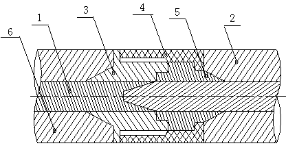
[0016] like figure 1 The transformer lead wire connection structure of the present invention shown includes a crepe paper insulation layer 6, copper rod A1 and copper rod B2, the copper rod A1 is connected to the copper rod B2 in a tapered shape, and the copper rod A1 and the copper rod B2 are surrounded by formed insulating threaded columns 3. The self-insulating layer formed by the formed insulating threaded sleeve 4 and the formed insulating sleeve 5 .

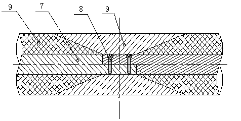
[0017] like figure 2 The traditional lead connection structure shown includes copper rod C7, bolt 8 and insulating layer 9. The copper rod A1 and copper rod B2 of the present invention are conically connected, replacing the traditional copper rod and bolt 8 crimping method, increasing the copper rod The effective connection area is improved, and the electrical conductivity is improved. Among them, the formed insulating thread column 3, the...


PUM


Abstract

The invention belongs to the technical field of transformer structures, and particularly relates to a transformer lead connection structure. The transformer lead connection structure comprises an insulating layer and copper rods. The transformer lead connection structure is characterized in that the copper rods include the copper rod A and the copper rod B, the copper rod A and the copper rod B are connected in a conical shape, and a self-insulating layer composed of a formed insulating threaded column, a formed insulating threaded sleeve and a formed insulating sleeve is arranged around the copper rod A and the copper rod B. The transformer lead connection structure is simple in structure and convenient to use; the copper A and the copper B are connected in the conical shape instead of a traditional compression joint mode between copper rods and bolts, so that the effective connection area of the copper rods is enlarged, and conductivity is improved; besides, manufacturing cost is low, and therefore popularization and application are facilitated.

Description

(1) Technical field [0001] The invention relates to a transformer lead wire connection structure, belonging to the technical field of transformer structures. (2) Background technology [0002] At present, the lead wires of power transformers with a voltage level of 110kV and above are mostly connected by copper rods and bolts. However, the connection area is small, the connection effect is poor, and the conductivity is not good. At the same time, the outside needs to be shielded and wrapped with an insulating layer. Extend working hours and increase labor intensity. (3) Contents of the invention [0003] In order to make up for the defects of the prior art, the invention provides a transformer lead wire connection structure with simple structure, which can increase the effective connection area of ​​copper rods and provide conductivity. [0004] The present invention is achieved through the following technical solutions: [0005] A transformer lead connection...

Claims


Application Information

Patent Timeline
Patent Type & Authority Applications(China)
IPC IPC(8): H01F27/29H01F27/32
Inventor 陈尔刚魏鸣跃李振
Owner SHANDONG DACHI ELECTRIC
Learn More