Low row steam generator inspection probe

A technology of detectors and inspection groups, applied to the primary side of steam generators, steam generation, steam boilers, etc., can solve problems such as impossible inspection, traveling of tubular parts, and device jamming

Inactive Publication Date: 2014-06-25
GENERAL ELECTRIC CO
View PDF5 Cites 5 Cited by
  • Summary
  • Abstract
  • Description
  • Claims
  • Application Information

AI Technical Summary

Problems solved by technology

However, it is possible to know that the device has become stuck, or otherwise unable to travel along the tubular member, making further inspection impossible

Method used


Image

  • Low row steam generator inspection probe
  • Low row steam generator inspection probe
  • Low row steam generator inspection probe

Examples


Embodiment Construction

[0014] Illustrative embodiments incorporating one or more aspects of the present invention are described and illustrated in the drawings. These illustrated examples are not intended to be a general limitation of the invention. For example, one or more aspects of the invention can be used in other embodiments and even other types of devices. Furthermore, certain terms are used herein for convenience only and are not to be construed as limitations of the present invention. Also, in the drawings, the same reference numerals are used to designate the same elements.

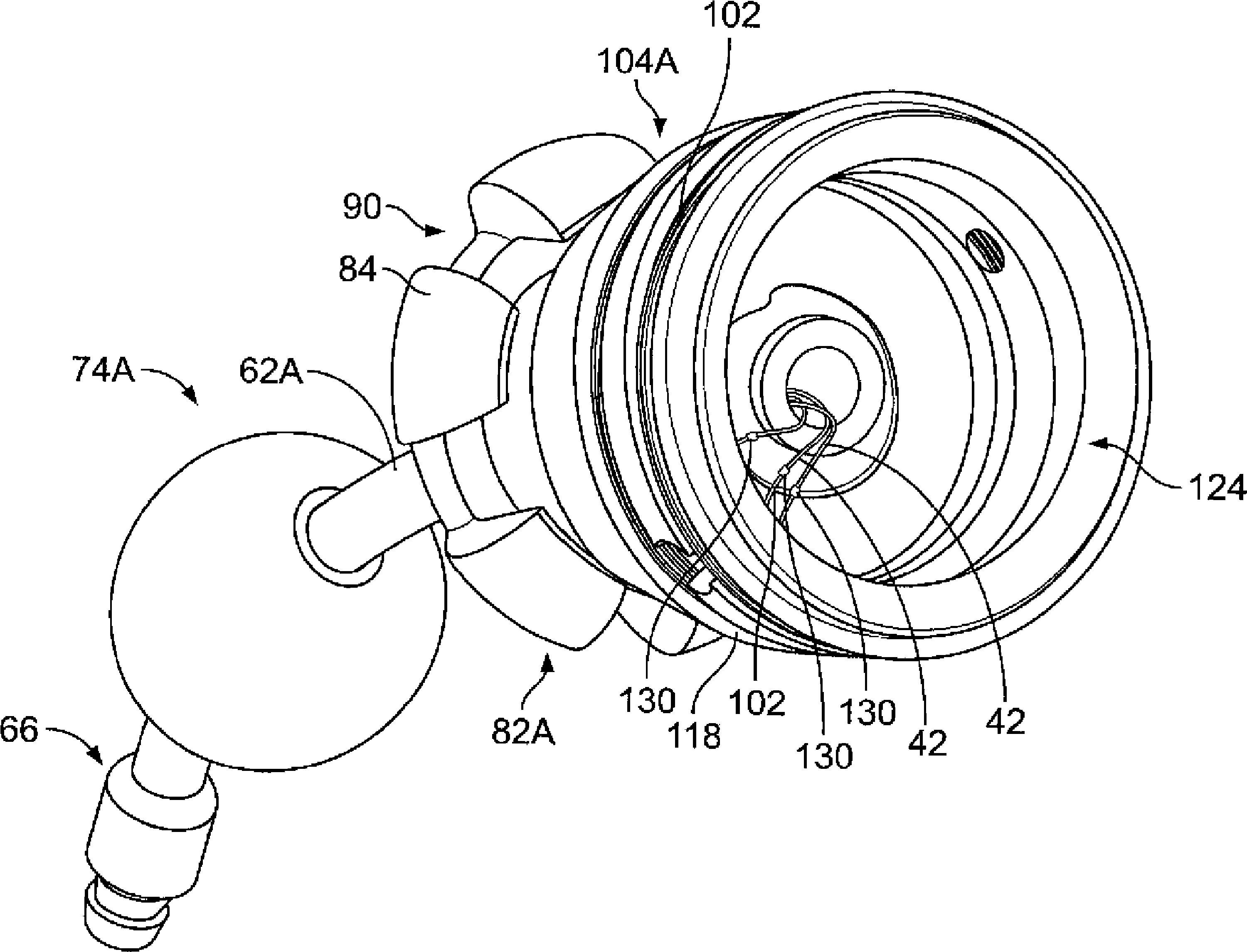
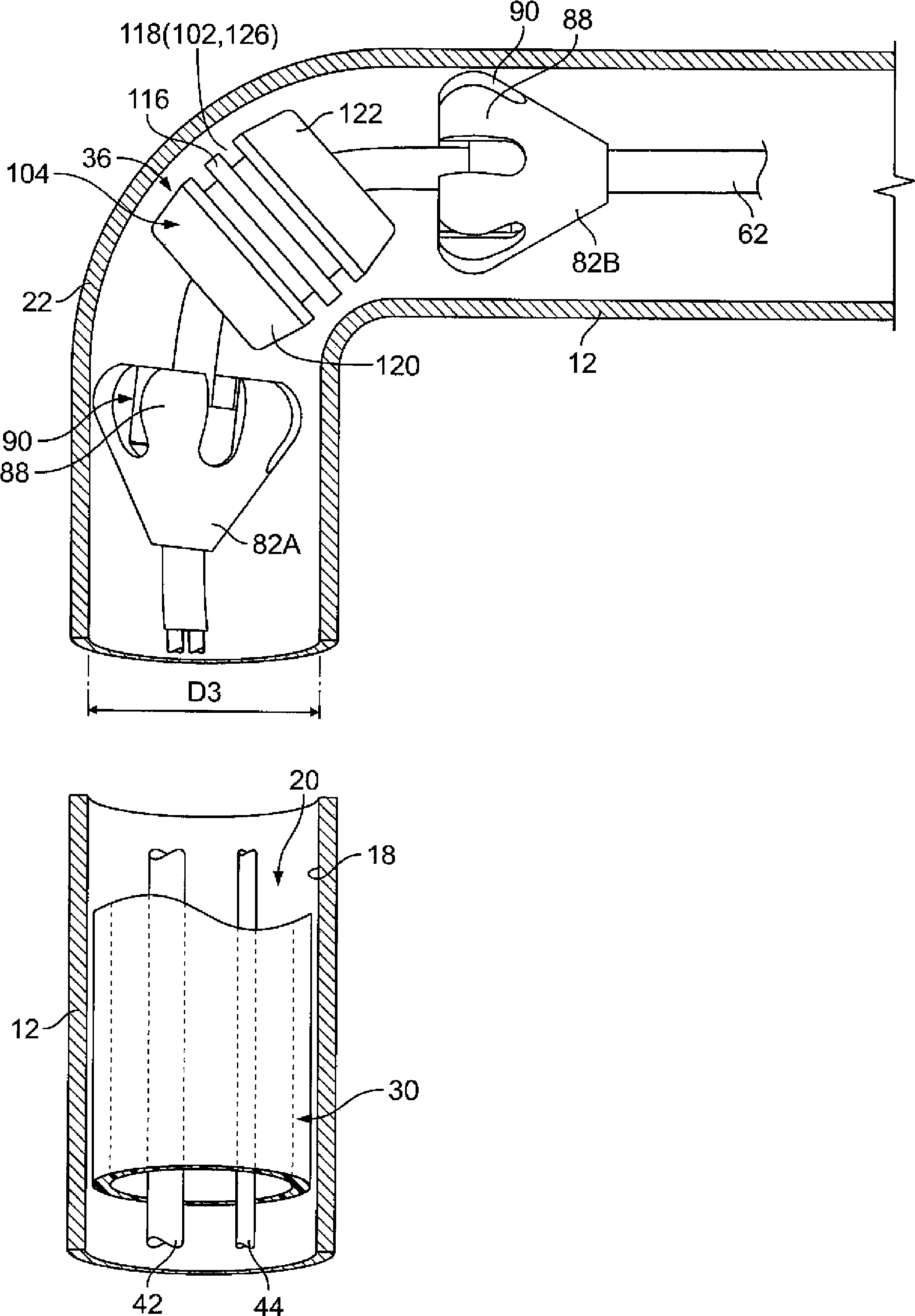
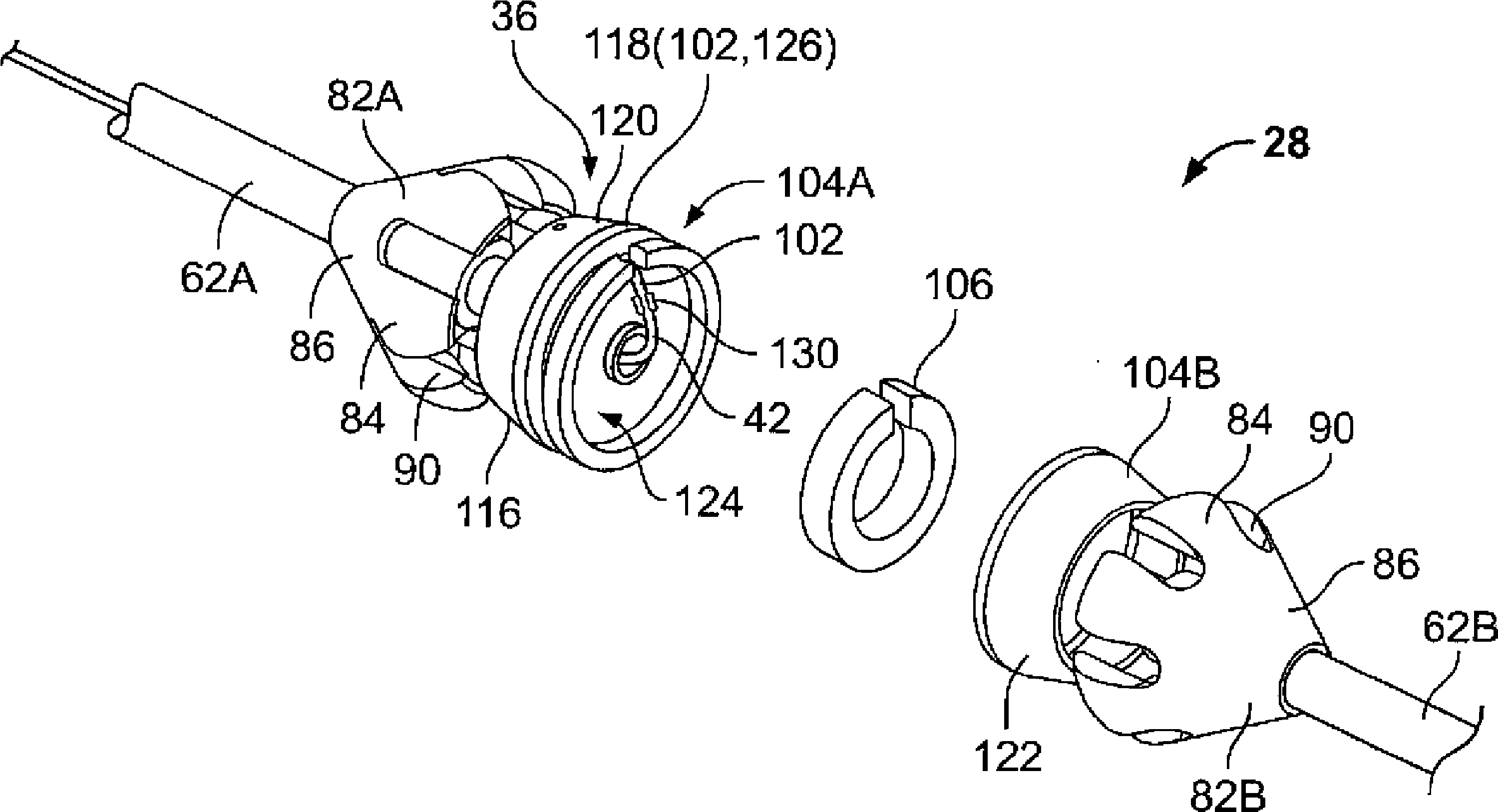
[0015] exist figure 1 An example of an inspection assembly 10 according to aspects of the invention is schematically shown in . It should be appreciated that the examples are for illustration purposes only and do not necessarily suggest specific limitations on the scope of the invention. Inspection assembly 10 is used for elongated tubular member 12 (for example, see in figure 2 Insertion inspection of the tubul...


PUM


Abstract

The invention provides an inspection assembly for insertion inspection of an elongate tubular member. The inspection assembly includes a probe head with a sensor. The assembly also includes a flexible shaft connected to the probe head and transmitting a motive force to the probe head to move the probe head within the elongate tubular member. The probe head includes at least one characteristic to minimize resistance against movement of the probe head along a torturous path within the tubular member.

Description

technical field [0001] The present invention relates to internal inspection probes for inspecting tubular components such as those found in nuclear steam generators. Background technique [0002] The use of inspection / detection devices such as eddy current sensors is known. For example, such devices may be used with nuclear power generator tubular components having meandering bends (eg, u-bends). However, it is possible to know that the device has become stuck, or otherwise unable to travel along the tubular member, making further inspection impossible. Therefore, improvements are required to avoid such problems. Contents of the invention [0003] The following overview presents a brief overview in order to provide a basic understanding of some aspects of the systems and / or methods described herein. This summary is not an extensive overview of the systems and / or methods described herein. It is not intended to identify key / critical elements or to delineate the scope of ...

Claims


Application Information

Patent Timeline
Patent Type & Authority Applications(China)
IPC IPC(8): F22B37/00G01N27/90G21C17/017G21D1/00
CPCG21D1/006F22B37/003G21C17/017G01N27/9006Y02E30/30
Inventor J·B·德拉珀M·B·沃尔夫M·A·特哈L·E·马吉
Owner GENERAL ELECTRIC CO
Why Eureka
Try Eureka