
Uplink control method and apparatus in wireless communication system

A wireless communication system and link technology, applied in the field of access from a mobile station (MS) to a base station (BS), and can solve problems such as difficulty in applying beamforming systems

Active Publication Date: 2014-06-25
SAMSUNG ELECTRONICS CO LTD
View PDF3 Cites 124 Cited by
  • Summary
  • Abstract
  • Description
  • Claims
  • Application Information

AI Technical Summary

Problems solved by technology

However, there is a disadvantage that since this technique is based on a system using an omnidirectional antenna, it is difficult to apply to a beamforming system that causes different path losses depending on transmit / receive beam directions

Method used


Image

  • Uplink control method and apparatus in wireless communication system
  • Uplink control method and apparatus in wireless communication system
  • Uplink control method and apparatus in wireless communication system

Examples


Embodiment Construction

[0034] The following description, with reference to the accompanying drawings, is provided to assist in a comprehensive understanding of exemplary embodiments of the invention as defined by the claims and their equivalents. Various specific details are included to assist in that understanding but are regarded as merely illustrative. Accordingly, those of ordinary skill in the art will recognize that various changes and modifications of the embodiments described herein can be made without departing from the scope and spirit of the invention. Also, descriptions of well-known functions and constructions may be omitted for clarity and conciseness.

[0035] The terms and words used in the following description and claims are not limited to the bibliographical meanings, but, are merely used by the inventor to enable a clear and consistent understanding of the invention. Accordingly, it will be apparent to those skilled in the art that the following descriptions of exemplary embodim...


PUM


Abstract

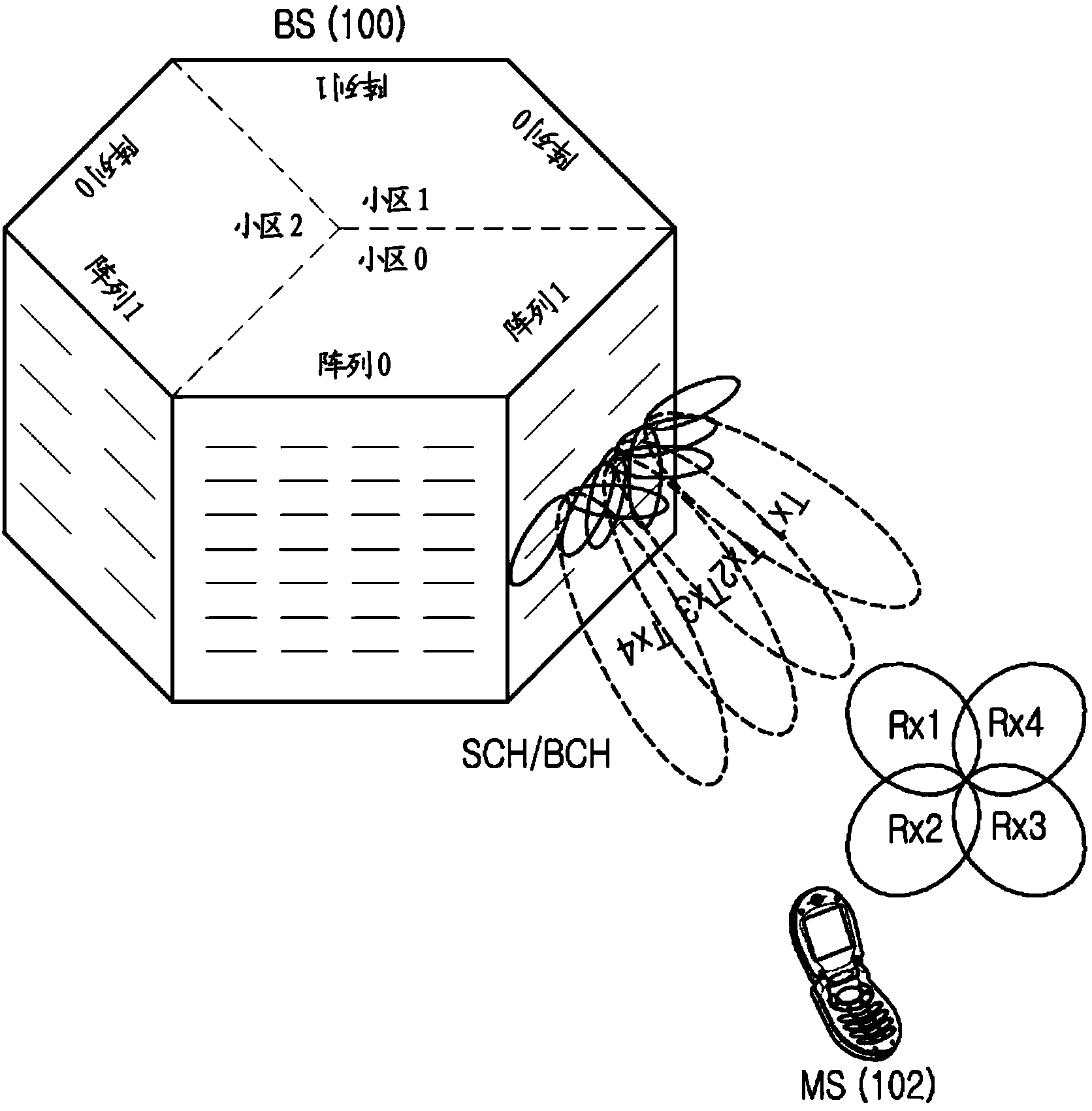
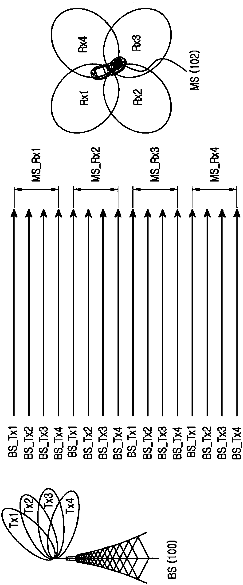
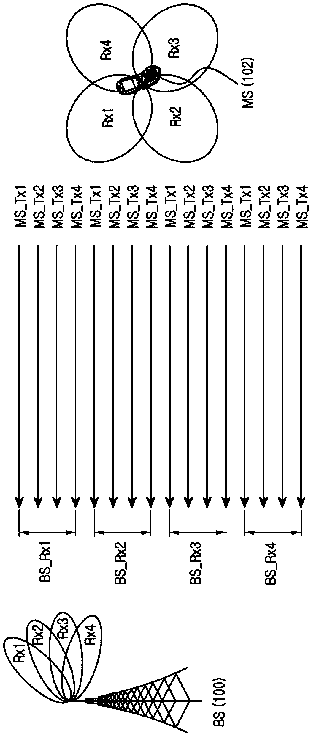
An UpLink (UL) control method and apparatus for in a wireless communication system supporting beamforming are provided. A method of a Mobile Station (MS) for UL control in the wireless communication system supporting the beamforming includes receiving a plurality of DownLink (DL) reference signals from a plurality of Base Station (BS) transmission beams using a plurality of MS reception beams having different directivity, measuring a path loss based on a reception signal strength of each of the plurality of DL reference signals received through different transmission / reception beams, selecting an MS transmission beam for uplink based on the path loss value measured for each of the plurality of DL reference signals, and transmitting a UL signal to a BS using the selected MS transmission beam.

Description

technical field [0001] The present invention relates to an uplink (UL) control method and device in a wireless communication system. More particularly, the present invention relates to a UL control method for access of a mobile station (MS) to a base station (BS) in a wireless communication system. Background technique [0002] The average amount of data used by a mobile communication subscriber has increased geometrically, and user demands for higher data transmission rates have increased at a similar rate. In order to address this increasing demand for a high data transmission rate, research is being conducted for introducing an ultra-high frequency band communication technology of 30G Hertz (GHz) or higher, that is, a millimeter wave system. [0003] In mmWave systems, severe propagation path loss occurs, and the coverage of BS is significantly reduced. In order to solve this problem in the millimeter wave system, it is expected to introduce a beamforming technique that...

Claims


Application Information

Patent Timeline
IPC IPC(8): H04B7/04H04W52/24
Inventor 郑丁寿
Owner SAMSUNG ELECTRONICS CO LTD
Learn More