Wo-part particle filter and method for producing the same

A particle filter and filter technology, which can be used in fixed filter element filters, chemical instruments and methods, filtration and separation, etc., can solve the problems of difficult filter technology and high realization cost.

Inactive Publication Date: 2014-07-02
ROBERT BOSCH GMBH
View PDF8 Cites 1 Cited by
  • Summary
  • Abstract
  • Description
  • Claims
  • Application Information

AI Technical Summary

Problems solved by technology

The dimensions of the filter to remove the smallest particles are technically very difficult or cost prohibitive to achieve

Method used


Image

  • Wo-part particle filter and method for producing the same
  • Wo-part particle filter and method for producing the same
  • Wo-part particle filter and method for producing the same

Examples


Embodiment Construction

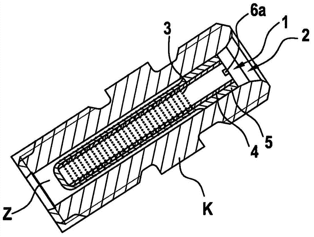
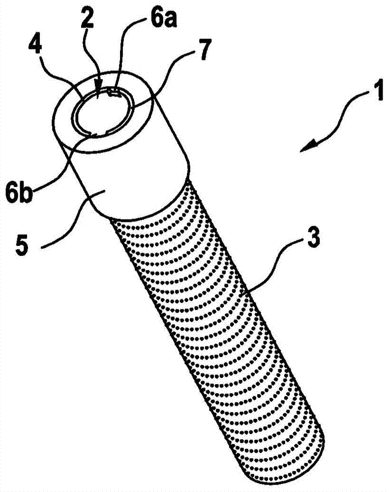
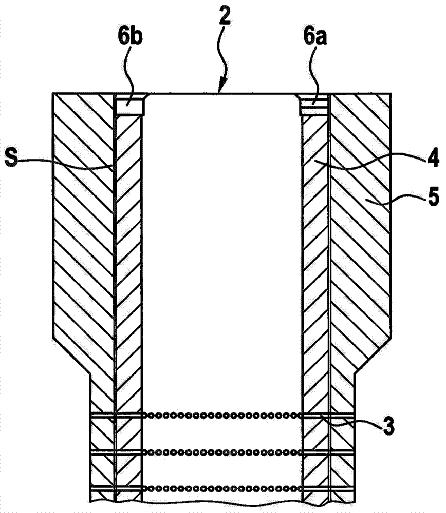
[0029] figure 1 A particle filter is shown which comprises a rod-shaped filter body 1 which is inserted into an inlet channel Z of a fuel injection device K. FIG. The rod filter body 1 consists of a first and a second rod bushing 4 , 5 . Since the rod-shaped filter body is arranged in a high-pressure system, the two rod-shaped filter bodies 4 , 5 are made of metallic material. Here, a first rod-shaped filter bush 4 is inserted into a second rod-shaped filter bush 5 . The rod-shaped filter body 1 also has an inlet 2 on one end face, through which the fluid flows into the particle filter. A plurality of outlets 3 are arranged on the housing surface of the filter body 1 through which the fluid flows out of the filter body 1 again.

[0030] The cross-section of the outlet 3 is dimensioned such that the fluid is filtered and particles whose diameter is larger than the diameter of the outlet 3 cannot escape from the rod-shaped filter body 1 . The cross-section of the outlet 3 is...


PUM


Abstract

The particle filter has a rod-shaped filter body (1), which is inserted in a feed channel (Z) of a fuel injector (K). The rod-shaped filter body has an inlet opening (2) and multiple outlet openings (3) arranged on a lateral surface of the rod-shaped filter body. The rod-shaped filter body has a first and a second rod-shaped connectors (4,5), where the first rod-shaped connector is inserted into the second rod-shaped connector.

Description

technical field [0001] The invention relates to a particle filter comprising a rod-shaped filter body which is introduced into an inlet channel of a fuel injection device, wherein the rod-shaped filter body has at least one inlet and a plurality of An outlet arranged on the outer surface of the rod-shaped filter body. [0002] The invention also relates to a method of manufacturing such a particle filter. Background technique [0003] Liquid or gas directing components on injection systems should be rated to pass particles that are too large to pass through the particle filter before entering said liquid or gas directing component to preserve its function. The particulate filter should be installed on each component in addition to the system filter so that the component prevents the ingress of not only other system components assembly impurities when loaded with particles, but also particles that may be generated during runtime into the system components . [0004] Not on...

Claims


Application Information

Patent Timeline
Patent Type & Authority Applications(China)
IPC IPC(8): B01D29/11F02M61/16
CPCB01D29/35F02M2200/27B01D29/111F02M61/165B01D29/58
Inventor H·克劳斯A·克默特
Owner ROBERT BOSCH GMBH
Why Eureka
Try Eureka