
Automatic riveting device of transformer

An automatic riveting and transformer technology, which is applied in the manufacture of inductors/transformers/magnets, electrical components, circuits, etc., can solve the problems of low automation, high riveting requirements, and low production efficiency, and achieve high automation and riveting good effect

Inactive Publication Date: 2014-07-02
XUZHOU GLORIA TECH
View PDF7 Cites 3 Cited by
  • Summary
  • Abstract
  • Description
  • Claims
  • Application Information

AI Technical Summary

Problems solved by technology

[0002] During the manufacturing process of the transformer, there is a process of wrapping a layer of iron cover on the outside of the iron core. The cover is required to wrap and fix the iron core tightly. This requires high riveting of the cover. Generally, transformer manufacturers here The first process is all manual operation, the degree of automation is extremely low. Due to manual operation, the production efficiency is low, and the effect of the casing wrapping is not good. In today's increasingly competitive market, how to improve production efficiency and product quality has become a production process. Determinants of a manufacturer's survival

Method used


Image

  • Automatic riveting device of transformer
  • Automatic riveting device of transformer

Examples


Embodiment Construction

[0012] The present invention will be further described below in conjunction with accompanying drawing.

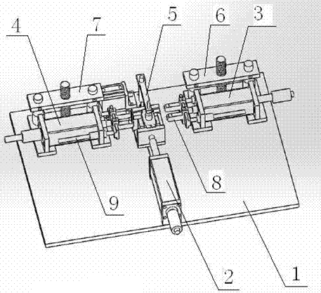
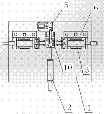
[0013] Such as figure 1 and figure 2 shown (in figure 2 The front direction is the upward direction), the transformer automatic riveting device, including the bottom plate 1, side fixing frame 2, right riveting frame 3, left riveting frame 4, upper fixing frame 5 and transformer mounting base 10, transformer mounting base 10 Fixed on the bottom plate 1, the upper fixing frame 5, the side fixing frame 2, the left riveting frame 4, and the right riveting frame 3 are respectively located in the up, down, left, and right directions of the transformer mounting base 10, and the upper fixing frame 5 and the side fixing frame 2 are fixed on the bottom plate 1, the left riveting frame 4 and the right riveting frame 3 are respectively fixed on the bottom plate 1 through the left adjusting frame 7 and the right adjusting frame 6, and the left adjusting frame 7 and the right adjust...


PUM


Abstract

The invention discloses an automatic riveting device of a transformer. The automatic riveting device comprises a bottom plate (1), a side fixing frame (2), a right riveting frame (3), a left riveting frame (4), an upper fixing frame (5) and a transformer installing base (10). The transformer installing base is fixed to the bottom plate. The upper fixing frame, the side fixing frame, the left riveting frame and the right riveting frame are located on the upper side, the lower side, the left side and the right side of the transformer installing base respectively. The upper fixing frame and the side fixing frame are fixed to the bottom plate, and the left riveting frame and the right riveting frame are fixed to the bottom plate through a left adjusting frame (7) and a right adjusting frame (6) respectively. The inner side of the left riveting frame and the inner side of the right riveting frame are respectively provided with a riveting head (8). The side fixing frame, the upper fixing frame, the left riveting frame and the right riveting frame are all connected with a controller. In the riveting process of an iron core outer housing, manual participation steps are fewer, after the transformer is manually placed on the transformer installing base, the controller controls the parts to fix and rivet the transformer, and the automation degree is high and the riveting effect is good in the whole process.

Description

technical field [0001] The invention relates to an automatic riveting device for a transformer, which belongs to the technical field of transformer production. Background technique [0002] During the manufacturing process of the transformer, there is a process of wrapping a layer of iron cover on the outside of the iron core. The cover is required to wrap and fix the iron core tightly. This requires high riveting of the cover. Generally, transformer manufacturers here The first process is all manual operation, the degree of automation is extremely low. Due to manual operation, the production efficiency is low, and the effect of the casing wrapping is not good. In today's increasingly competitive market, how to improve production efficiency and product quality has become a production process. Determinants of the survival of manufacturers. Contents of the invention [0003] Aiming at the above-mentioned problems in the prior art, the present invention provides an automatic...

Claims


Application Information

Patent Timeline
Patent Type & Authority Applications(China)
IPC IPC(8): B21D39/00H01F41/00
Inventor 张亮夏永文
Owner XUZHOU GLORIA TECH
Learn More