
A controllable contact pressure polishing device

A polishing device and contact pressure technology, applied in the direction of grinding/polishing equipment, optical surface grinder, workpiece feed movement control, etc., to achieve the effects of alleviating medium and high frequency errors, good consistency, and improving surface shape accuracy

Active Publication Date: 2017-04-26
吉林省神农氏机器人科技有限公司
View PDF7 Cites 0 Cited by
  • Summary
  • Abstract
  • Description
  • Claims
  • Application Information

AI Technical Summary

Problems solved by technology

[0004] In order to solve the problem that the existing controllable contact pressure polishing tool obtains the precise position of the linear sliding table slide plate fixedly connected with the polishing spindle, and determines the current value input to the voice coil motor according to the position information, a controllable contact pressure polishing tool is further proposed. contact pressure polishing unit

Method used


Image

  • A controllable contact pressure polishing device

Examples


specific Embodiment approach 1

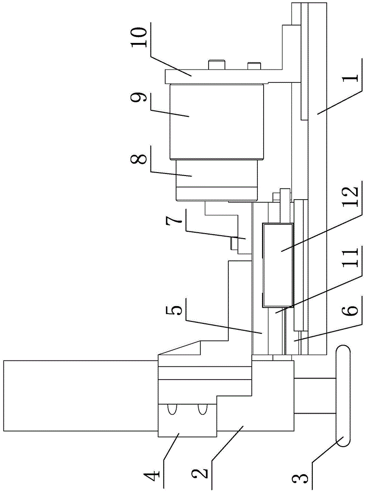
[0008] Specific implementation mode one: combine figure 1 Describe this embodiment, a controllable contact pressure polishing device described in this embodiment includes a polishing tool base 1, a polishing spindle 2, a polishing wheel 3, a polishing spindle connector 4, a linear slide slide 5, a linear slide base Seat 6, voice coil motor coil connector 7, voice coil motor and voice coil motor magnetic steel connector 10, polishing tool base 1 is horizontally arranged, polishing main shaft 2 is vertically arranged on one end of polishing tool base 1, and polishing main shaft 2 The axis is perpendicular to the upper surface of the polishing tool base 1, the polishing wheel 3 is installed on the lower end of the polishing spindle 2, the polishing spindle 2 is connected to the front of the linear slide slide 5 through the polishing spindle connector 4, and the linear slide slide 5 is installed on the polishing tool base 1 through the linear slide base 6, and the voice coil motor...

specific Embodiment approach 2

[0010] Specific implementation mode two: combination figure 1 To illustrate this embodiment, a controllable contact pressure polishing device described in this embodiment also includes a grating 11 and a reading head 12, the grating 11 is installed on the slide plate 5 of the linear slide table, and the reading head 12 is installed on the polishing tool base 1 At the front, the read head 12 is used to read the position signal on the grating 11 .

[0011] The technical effect of this embodiment is: set in this way, in the process of polishing pressure control, after the command of the controlled contact pressure value is issued, the precise position of the linear sliding table slide plate fixedly connected with the polishing spindle is obtained by the grating and the reading head, according to this The position information determines the value of the current input to the voice coil motor. Other components and connections are the same as those in the first embodiment.

[0012]...


PUM


Abstract

The invention relates to a polishing device, in particular to a controllable contact pressure polishing device, and aims to solve the problem that the existing controllable contact pressure polishing tools brings in certain medium-high frequency errors and large difficulty is brought to further surface shape precision increasing. The polishing spindle of the polishing device is vertically disposed at one end of a polishing tool base. The axis of the polishing spindle is vertical to the upper surface of the polishing tool base. A polishing wheel is mounted at the lower end of the polishing spindle. The polishing spindle is connected to the front portion of a linear slipway slide carriage through a connector. The linear slipway slide carriage is mounted on the polishing tool base through a linear slipway base. The voice coil motor coil of a voice coil motor is connected to the rear portion of the linear slipway slide carriage through a voice coil motor coil connector. The voice coil motor magnetic steel of the voice coil motor is mounted on the rear portion of the polishing tool base through a voice coil motor magnetic steel connector. The controllable contact pressure polishing device is applicable to the field of precision optics machining.

Description

technical field [0001] The invention relates to a polishing device, in particular to a controllable contact pressure polishing device, which belongs to the field of precision optical processing. Background technique [0002] In the aspheric surface processing technology in the field of precision optical processing, it is necessary to polish the aspheric surface after milling to reduce the damage of the workpiece and the surface roughness of the workpiece, and improve the surface shape accuracy and surface quality of the workpiece to meet the actual use requirements. . Deterministic polishing technologies for aspheric surfaces mainly include magnetorheological polishing technology, airbag polishing technology, and CCOS polishing technology based on small tools. The basic working principle of determining the polishing technology is: firstly, through the process test of the sample, the accurate material removal function is obtained; secondly, the surface shape of the workpiece...

Claims


Application Information

Patent Timeline
Patent Type & Authority Patents(China)
IPC IPC(8): B24B13/00B24B49/16
CPCB24B13/00B24B49/165
Inventor 赵清亮饶志敏郭兵陈冰张全利程凯唐群瑞
Owner 吉林省神农氏机器人科技有限公司
Learn More