Heat treatment receiving device

A technology of receiving device and processing area, which is applied in the field of heat treatment receiving device, can solve the problems of small objects falling and accumulating, heavy burden, insufficient weight, etc., and achieve the effect of maintaining heat treatment efficiency, reducing cost and reducing consumption

Active Publication Date: 2015-11-04
METAL INDS RES & DEV CENT
View PDF4 Cites 0 Cited by
  • Summary
  • Abstract
  • Description
  • Claims
  • Application Information

AI Technical Summary

Problems solved by technology

[0006] Just, because the conveyor table 93 of this existing heat treatment receiving device 9 usually selects the conveyer belt 931 that has magnetism or tightly woven type, so if the small objects for heat treatment are made of non-magnetic materials, when the small objects are guided to leave In the process of the oil tank 92, the problem of small objects slipping and accumulating will often occur due to the inability to be magnetically attracted; even if the problem of magnetic attraction is not considered, these small parts often slip and accumulate due to insufficient friction with the conveyor belt 931 , thereby affecting the operating efficiency of the existing heat treatment receiving device 9
[0007] Furthermore, when the volume of the small objects to be heat treated is as small as miniature, such as watch parts such as miniature screws and gears, they are often suspended in the oil tank 92 because of their insufficient weight, and will not fall on the conveyor belt 931, so that they cannot be guided. Send out of oil tank 92
On the other hand, the large-volume oil tank 92 needs to be filled with a large amount of coolant before it can operate. Whether it is the cost of controlling the temperature of the coolant during operation or the cost of changing the coolant, it is a considerable burden.
[0008] In addition to the aforementioned existing heat treatment receiving device 9, the patent case of "Oil-Water Separation Device of Heat Treatment Furnace" announced by China Taiwan No. M431733 also uses a similar device to heat treat objects, so it also has the above-mentioned shortcomings; based on the above reasons, the existing It is indeed necessary to improve the heat treatment receiving device

Method used


Image

  • Heat treatment receiving device
  • Heat treatment receiving device

Examples


Embodiment Construction

[0054] In order to make the above-mentioned and other objects, features and advantages of the present invention more comprehensible, the preferred embodiments of the present invention are specifically cited below, together with the accompanying drawings, as follows:

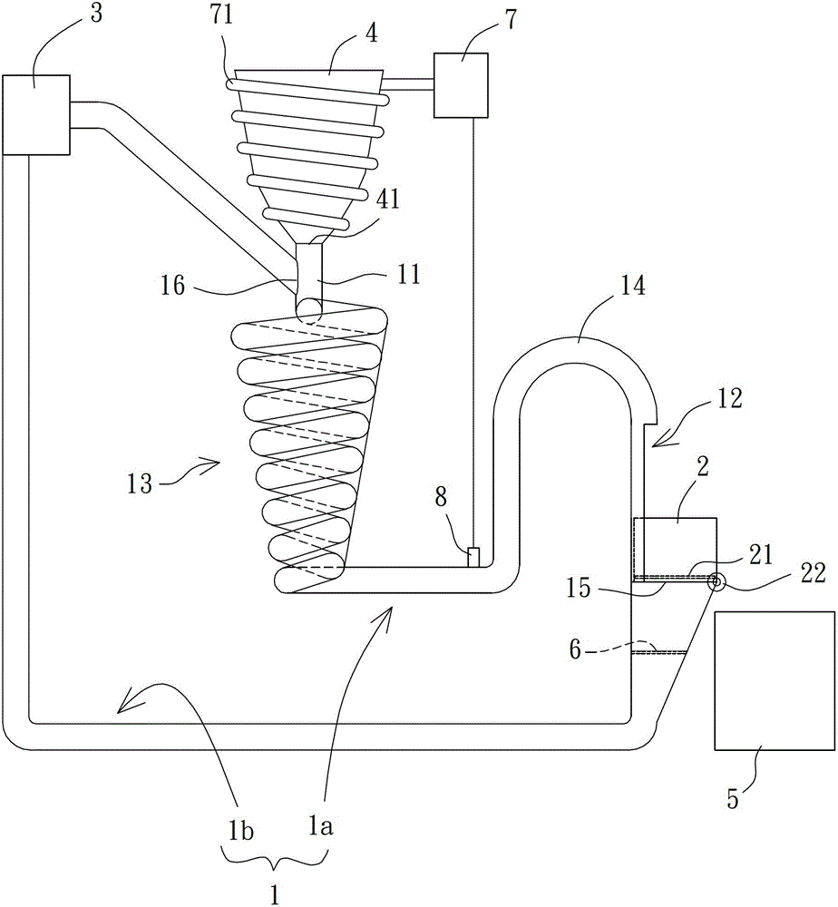
[0055] Please refer to figure 2 As shown, the heat treatment receiving device of the preferred embodiment of the present invention includes a circulation pipeline 1, a filter box 2 and a pressure member 3, and the circulation pipeline 1 is used to accommodate and transport cooling liquid to circulate Pipe body, the coolant can be water or oil, used to cool relatively high-temperature objects, the filter box 2 is located in the circulation pipeline 1, and the pressure member 3 is used to pressurize the coolant, so that the Coolant can circulate in the circulation line 1 .

[0056] The circulation pipeline 1 can be roughly divided into a processing area 1a and a recirculation area 1b which are connected. The cool...


PUM


Abstract

A heat treatment material collecting device is used for solving a problem of the heat treatment efficiency reduction caused by the unsmooth conveying of previous heat treatment objects. The device comprises: a circulation pipeline having a treatment zone and a recirculation zone, heat exchange of a liquid coolant and an object is carried out in the treatment zone, two ends of the treatment zone are a receiving portion and an opening respectively, one end of the recirculation zone faces the opening, and the other end of the recirculation zone is connected with the receiving portion; a filtering box arranged at the opening and provided with a first filter screen; and a pressurizing member connected with the circulation pipeline, arranged in the recirculation zone and used for pressuring the liquid coolant in order to make the liquid coolant circularly flow in the circulation pipeline.

Description

technical field [0001] The invention relates to a heat treatment receiving device, in particular to a heat treatment receiving device for cooling and tempering objects with cooling liquid. Background technique [0002] The so-called heat treatment is to change the material properties by controlling the temperature and adjusting the cooling rate; generally speaking, the objects of heat treatment are mostly solid metals. More specifically, metal materials have many fine crystals called grains under the microstructure. The size and composition of grains are the most decisive factors affecting the mechanical properties of metals. Heat treatment is to control the diffusion rate under the metal microstructure. and cooling rate to obtain the desired mechanical properties (eg hardness, stress-strain properties, toughness, ductility, elasticity, etc.). [0003] For example, for the heat treatment of small objects such as mechanical materials, hardware parts, automobile and motorcycl...

Claims


Application Information

Patent Timeline
Patent Type & Authority Patents(China)
IPC IPC(8): C21D1/00
Inventor 杨济华罗万中黄家宏卓廷彬黄怀谆
Owner METAL INDS RES & DEV CENT
Why Eureka
Try Eureka