Garbage disposal device capable of utilizing self-circulation pyrolysis gas for preheating air

A technology for waste treatment equipment and air preheating chambers, applied in lighting and heating equipment, combustion methods, indirect carbon dioxide emission reduction, etc., can solve problems such as uneven heat distribution, short residence time, waste of resources, etc., to improve reduction reaction Efficiency, reduction of pollutant emissions, consistent response

Active Publication Date: 2017-02-22
湖南省环境保护科学研究院
View PDF9 Cites 3 Cited by
  • Summary
  • Abstract
  • Description
  • Claims
  • Application Information

AI Technical Summary

Problems solved by technology

[0004] For example, the uneven oxygen supply at the same level of the waste reaction device leads to different oxidation rates of waste at the same level, and the uneven distribution of the released heat, which makes the reaction degree of the entire waste treatment device inconsistent; the residence time of the gas generated by the heat treatment of waste in the reaction device Shorter, the high calorific value components volatilized during the heat treatment process such as CO, CH4, H2, etc. are not fully oxidized, resulting in a great waste of resources; while the low calorific value components such as aromatic alcohol and heavy oil produced during the heat treatment process The residence time in the medium is too short, not fully decomposed, which increases the difficulty of tail gas treatment; because the average calorific value of the waste itself is low, the heat absorbed by the reduction reaction is taken away by the gas components with high calorific value, which is not conducive to the realization of the waste heat treatment device using the waste itself. The calorific value forms high temperature conditions; in addition, when the existing waste thermal treatment equipment provides the required oxygen (air) for the thermal reaction of waste, it does not preheat the air entering the reaction device, which is not conducive to the stable thermal reaction of waste

Method used


Image

  • Garbage disposal device capable of utilizing self-circulation pyrolysis gas for preheating air
  • Garbage disposal device capable of utilizing self-circulation pyrolysis gas for preheating air
  • Garbage disposal device capable of utilizing self-circulation pyrolysis gas for preheating air

Examples


Embodiment Construction

[0072] The technical solutions of the present invention will be clearly and completely described below in conjunction with the accompanying drawings. Apparently, the described embodiments are some of the embodiments of the present invention, but not all of them. Based on the embodiments of the present invention, all other embodiments obtained by persons of ordinary skill in the art without making creative efforts belong to the protection scope of the present invention.

[0073] In the description of the present invention, it should be noted that the terms "center", "upper", "lower", "left", "right", "vertical", "horizontal", "inner", "outer" etc. The indicated orientation or positional relationship is based on the orientation or positional relationship shown in the drawings, and is only for the convenience of describing the present invention and simplifying the description, rather than indicating or implying that the referred device or element must have a specific orientation, ...


PUM


Abstract

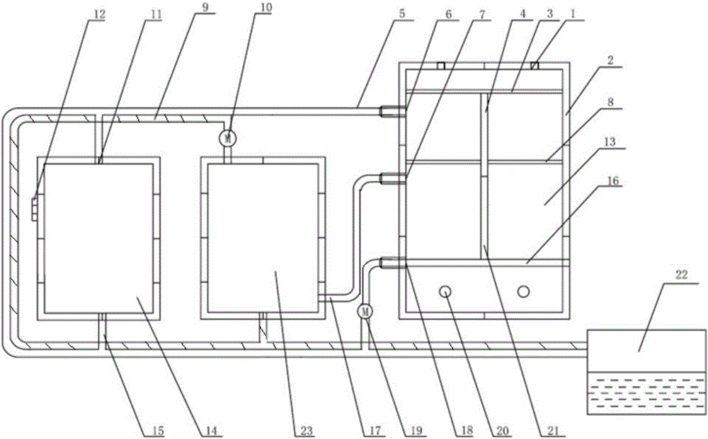
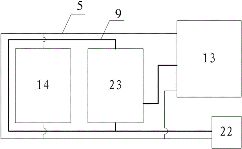
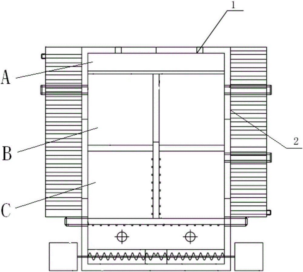
The invention discloses a garbage disposal device capable of utilizing self-circulation pyrolysis gas for preheating air. The device comprises a feeding opening, a garbage pyrolysis furnace wall, a first horizontal heat conduction plate, a vertical heat conduction plate, a first smoke circular pipeline, a top smoke circular pipeline connection opening, a tail gas pipeline connection opening, a second horizontal heat conduction plate, a second smoke circular pipeline, a first induced draft fan, an air preheating cavity connection opening, a first air inlet, a garbage pyrolysis furnace, an air preheating cavity, an exhaust opening, a horizontal air distribution pipeline, a tail gas treatment pipeline, a bottom smoke circular pipeline connection opening, a second induced draft fan, an observation window, a vertical air distribution pipeline, a settling pond, a tail gas purification device, an air distribution system, a smoke circular system and other structures. According to the disposal device, the reduction reaction efficiency is improved, the garbage heat treatment efficiency is ensured; and meanwhile, the self-circulation pyrolysis gas can be used for preheating the air, it can be ensured that low-heat-value components such as aromatic alcohol and heavy oil can be sufficiently decomposed in the reaction, and pollutant emissions in the tail gas can be reduced.

Description

technical field [0001] The invention relates to the technical field of garbage treatment equipment, in particular to a garbage treatment equipment that uses self-circulating pyrolysis gas to preheat air. Background technique [0002] At present, the heat treatment technology of waste has attracted more and more people's attention. Garbage heat treatment technology mainly uses the heat released by the calorific value of the garbage itself during the oxidation process to create high-temperature conditions and carry out a series of physical and chemical reactions at high temperatures, and the reaction process needs to provide an appropriate amount of oxygen (air). The waste gas after the reaction is discharged into the atmosphere after treatment, and the remaining residue is discharged from the reaction device for further treatment. [0003] However, the composition of domestic waste in my country is complex, the size varies greatly, the average calorific value is low, and the...

Claims


Application Information

Patent Timeline
Patent Type & Authority Applications(China)
IPC IPC(8): F23G5/027F23G5/44F23L15/00F23J15/06F23J15/02F23J15/04
CPCF23G5/027F23G5/44F23G2201/30F23G2900/50204F23J15/02F23J15/04F23J15/06F23J2219/30F23L15/00Y02E20/34
Inventor 李二平陈浩云邱亚群余志元熊如意
Owner 湖南省环境保护科学研究院
Why Eureka
Try Eureka