Optional-position lockable hydraulic cylinder

An arbitrary position, locking technology, applied in the direction of fluid pressure actuating devices, etc., can solve the problems of reduced system reliability, increased hydraulic system volume, complex hydraulic control system, etc., to get rid of the dependence of manpower and reliable locking , intelligent high effect

Inactive Publication Date: 2014-07-02
HARBIN ENG UNIV
View PDF5 Cites 12 Cited by
  • Summary
  • Abstract
  • Description
  • Claims
  • Application Information

AI Technical Summary

Problems solved by technology

[0002] Hydraulic cylinders are widely used in the industrial field. In many applications, the piston rod in the hydraulic cylinder needs to stop at a certain position for a long time and bear a certain push and pull force. The general technical solution is to add a pressure maintaining circuit to the hydraulic system, but this kind of There are disadvantages in the scheme: firstly, the hydraulic control system of the hydraulic cylinder becomes complicated, and the volume of the hydraulic system increases; secondly, the continuous high pressure on one side of the hydraulic cylinder and in the hydraulic oil circuit will cause great damage to the piston seal and the hydraulic system. Therefore, the system reliability is reduced
There are also other technical solutions for hydraulic cylinders to be locked at any position, but they generally cannot withstand large forces after locking.

Method used


Image

  • Optional-position lockable hydraulic cylinder
  • Optional-position lockable hydraulic cylinder
  • Optional-position lockable hydraulic cylinder

Examples


Embodiment Construction

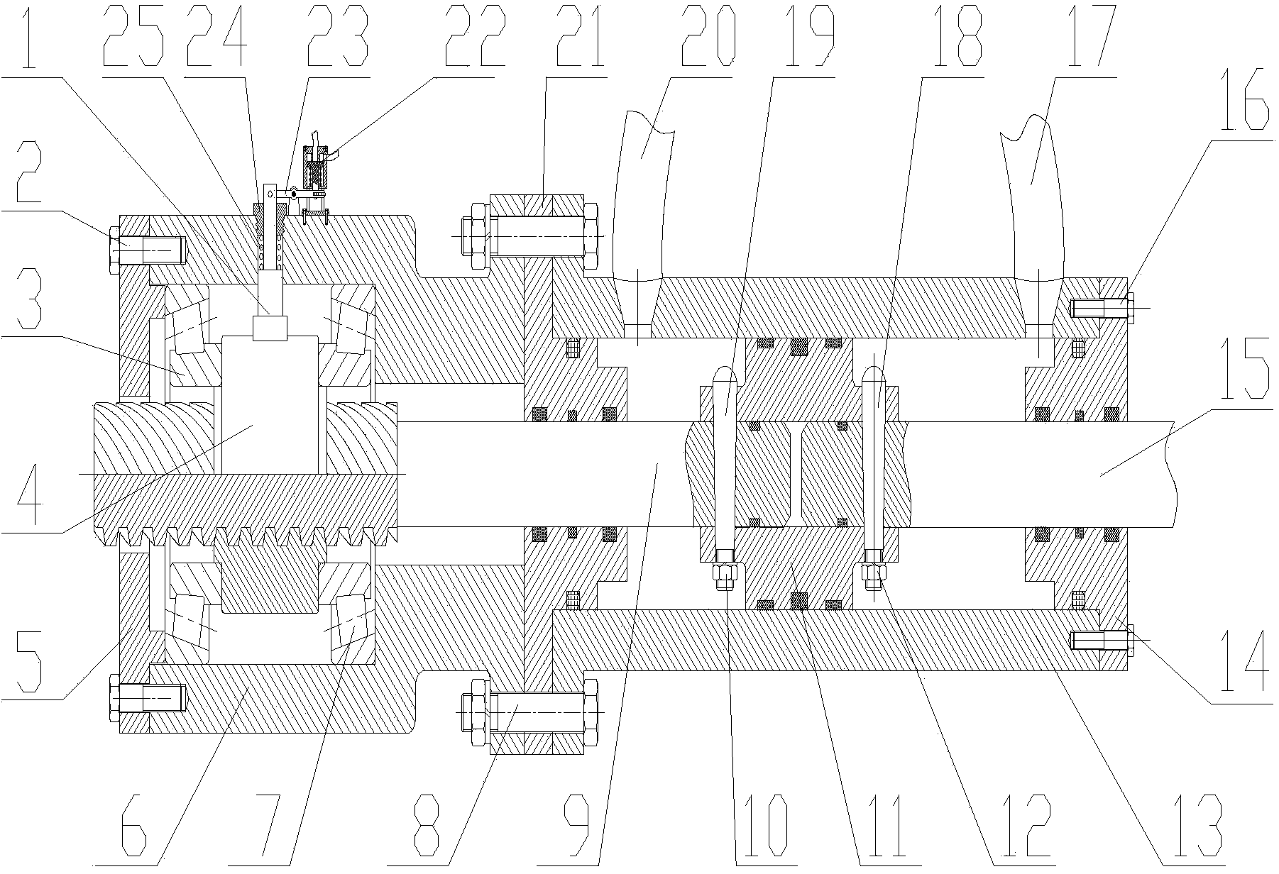
[0017] The present invention is described in more detail below in conjunction with accompanying drawing example:

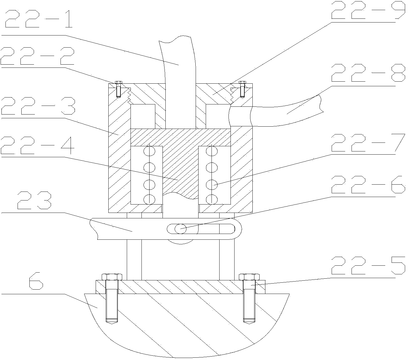
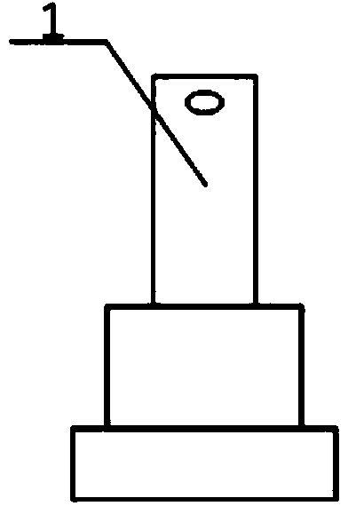
[0018] combine figure 1 ~3, the present invention mainly comprises hydraulic cylinder part 10~21, locking part 2~9 etc., locking control part 1, 22~25 etc.

[0019] The piston rod 15 is half penetrated into the cylindrical cavity of the piston 11, and transition fits therewith. The first conical pin 18 is provided with threads near the small end face, the first conical pin 18 passes through the hole on the piston 11 and the hole on the piston rod 15, and realizes the fixing of the piston 11 and the piston rod 15 by the second tightening nut 12 .

[0020] The piston rod 15 passes through the round hole of the front cover 14, and the front cover 14 is fixed on the cylinder block 13 by six third bolts 16, and the cylinder block 13 is provided with a first oil port 17 and a second oil port 20.

[0021] The outer contour of the locking box 6 is a stepped cylinder, a...


PUM


Abstract

The invention aims to provide an optional-position lockable hydraulic cylinder which comprises a cylinder body, a locking box body, a piston rod, a locking lever, a turning block and a lock claw. A front cover is fixed at the front end of the cylinder body, a rear cover is fixed at the rear end of the cylinder body, the locking box body is fixed on the rear cover, one end of the locking box body is fixed with a box cover, a piston is arranged in the cylinder body, a first oil mouth and a second oil mouth are respectively formed in the front end and the rear end of the cylinder body, one end of the piston rod is disposed in the piston, the left portion of the locking lever is located in the locking box body, the right end portion of the locking lever penetrates the rear cover to be disposed in the piston, the turning block provided with a cavity is disposed on the upper left portion of the locking lever, and a multihead trapezoidal thread of the turning block is arranged at the position of the cavity of the turning block and is engaged with a multihead trapezoidal thread of the locking lever. The optional-positional lockable hydraulic cylinder is simple and reliable in structure and especially suitable for being applied to occasions when the piston rod needs to stay in a certain position and bears larger pushing and pulling force.

Description

technical field [0001] The invention relates to a hydraulic device. Background technique [0002] Hydraulic cylinders are widely used in the industrial field. In many applications, the piston rod in the hydraulic cylinder needs to stop at a certain position for a long time and bear a certain push and pull force. The general technical solution is to add a pressure maintaining circuit to the hydraulic system, but this kind of There are disadvantages in the scheme: firstly, the hydraulic control system of the hydraulic cylinder becomes complicated, and the volume of the hydraulic system increases; secondly, the continuous high pressure on one side of the hydraulic cylinder and in the hydraulic oil circuit will cause great damage to the piston seal and the hydraulic system. Therefore, system reliability is reduced. There are other technical solutions for locking the hydraulic cylinder at any position, but generally it cannot withstand a large force after locking. Contents of ...

Claims


Application Information

Patent Timeline
Patent Type & Authority Applications(China)
IPC IPC(8): F15B15/26F15B15/14
Inventor 刘少刚潘方冬闫海峰刘铮魏春红宋建鑫吴长龙姚磊吴伟峰曾杏
Owner HARBIN ENG UNIV
Why Eureka
Try Eureka