Method and system for transmitting services between RRU and BBUs, and BBUs

A technology of service transmission and implementation method, applied in the field of BBU, can solve problems such as inability to transmit service data and lack of protection of optical paths, and achieve the effect of short switching time, few switching steps, and ensuring service perception

Active Publication Date: 2014-07-02
CHINA MOBILE GROUP ANHUI
View PDF6 Cites 8 Cited by
  • Summary
  • Abstract
  • Description
  • Claims
  • Application Information

AI Technical Summary

Problems solved by technology

[0004] In order to solve the technical problem in the prior art that one BBU supports multiple RRUs, the lack of protection of the optical path between the RRU and the BBU will easily lead to the failure of service data transmission. The present invention proposes a service transmission between the RRU and the BBU. Implementation method, system and BBU of

Method used


Image

  • Method and system for transmitting services between RRU and BBUs, and BBUs
  • Method and system for transmitting services between RRU and BBUs, and BBUs
  • Method and system for transmitting services between RRU and BBUs, and BBUs

Examples


Embodiment 1

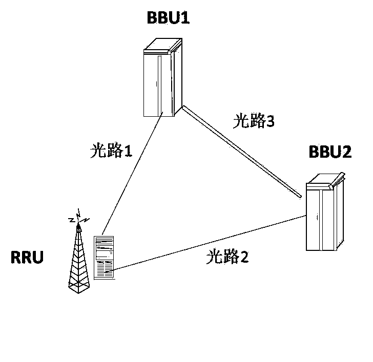
[0028] This embodiment combines figure 2 The shown networking diagram provides a method for implementing service transmission between the RRU and the BBU. like figure 2 As shown, the RRU belongs to (that is, connects) to two different BBUs, namely BBU1 and BBU2. BBU1, BBU2 and RRU can be connected through optical cables. Optical path 1 is between the RRU and BBU1; optical path 2 is between the RRU and BBU2.

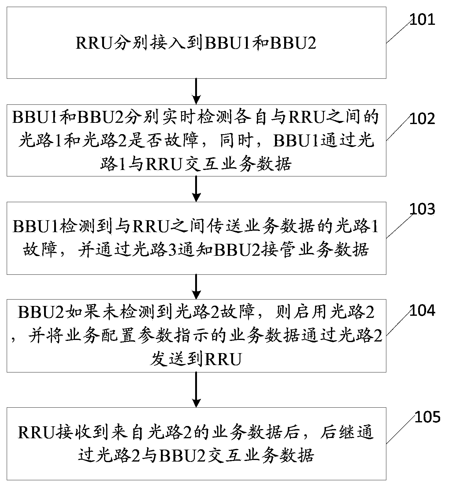
[0029] After the RRU is connected to the BBU1, the BBU1 sends a heartbeat message to the RRU at regular intervals to check whether the optical path 1 is smooth. If the BBU1 does not receive the heartbeat response message fed back by the RRU within the specified time, it is determined that the optical path 1 between the BBU1 and the RRU is faulty;

[0030] Similarly, after the RRU2 is connected to the BBU2, the BBU2 sends a heartbeat message to the RRU at regular intervals to check whether the optical path 2 is smooth. If the BBU2 does not receive the heartbeat resp...

Embodiment 2

[0044] In order to facilitate the implementation of the method in Embodiment 1, this embodiment provides a BBU, such as Figure 4 As shown, it includes: a connection module 21 , a fault detection module 22 and a switching module 23 .

[0045] A connection module 21, used for RRU access and establishing a connection with another BBU;

[0046] The fault detection module 22 is used to detect in real time whether the optical path of the optical port between the RRU and the RRU is faulty, and the service data is transmitted through the optical path of the optical port;

[0047] The switching module 23 is used to notify another BBU to take over the service data if the fault detection module 22 detects a fault in the optical path of the optical port channel when the optical path of the optical port channel is used to transmit business data with the RRU; or the switching module 23 It is used to take over the service data of another BBU when receiving the notification of taking over s...

Embodiment 3

[0055] This embodiment provides a system for implementing service transmission between the RRU and the BBU, such as Figure 5 As shown, it includes RRU10 and two BBUs, and the two BBUs are BBU1 and BBU2 respectively;

[0056] RRU10 is used to connect to BBU1 and BBU2 respectively;

[0057] BBU1 is used to detect in real time whether the optical port channel optical path 1 and optical port channel optical path 2 between each of them and RRU10 are faulty, wherein the service data is transmitted through optical port channel optical path 1 between BBU1 and RRU; When the optical port channel optical path 1 that transmits business data fails, notify BBU2 to take over the business data;

[0058] BBU2 is used to detect in real time whether the optical port channel optical path 1 and optical port channel optical path 2 between each and RRU10 are faulty, wherein the service data is transmitted through optical port channel optical path 1 between BBU1 and RRU; and when receiving the noti...


PUM


Abstract

The invention discloses a method and system for transmitting services between an RRU and BBUs, and the BBUs, and relates to the technical field of communication. The technical problem that in the prior art, protection is lacking in service transmission between the RRU and the BBUs is solved. The method includes the steps that firstly, the RRU has access to the BBU 1 and the BBU 2; secondly, the BBU 1 detects whether faults happen to a light path 1 between the BBU 1 and the RRU or not in real time, and the BBU 2 detects whether faults happen to a light path 2 between the BBU 2 and the RRU or not in real time, wherein service data are transmitted through the light path 1 between the BBU 1 and the RRU; thirdly, when the BBU 1 detects that faults happen to the light path 1 for transmitting the service data between the BBU 1 and the RRU, the BBU 2 is informed to take over all the service data; fourthly, the BBU 2 starts to use the light path 2 between the BBU 2 and the RRU to transmit the service data to the RRU.

Description

technical field [0001] The present invention relates to the field of communication technology, in particular to a method, system and BBU for realizing service transmission between RRU and BBU. Background technique [0002] The 3G network uses a large number of distributed base station architectures, that is, the networking form of BBU (baseband processing unit) + RRU (radio remote module), such as figure 1 As shown, the RRU and the BBU are connected by optical fibers. A BBU can support one or more RRUs. Optical fiber transmission is used between BBU and RRU, and RRU is connected to the antenna through coaxial cable and power divider (coupler), that is, optical fiber is used for the backbone, coaxial cable is used for the branch, and baseband digital signal transmission is used between BBU and RRU , can greatly reduce the interference on other channels in the cell, and is also very flexible for capacity configuration. [0003] However, the networking form in which one BBU ...

Claims


Application Information

Patent Timeline
Patent Type & Authority Applications(China)
IPC IPC(8): H04B10/075H04W24/04
Inventor 李方正王滨欧阳燕孙军李志国左鑫朱文武
Owner CHINA MOBILE GROUP ANHUI
Why Eureka
Try Eureka