Implementation method, system and bbu for service transmission between rru and bbu
A technology of service transmission and implementation method, applied in the field of BBU, can solve problems such as lack of protection of optical paths and inability to transmit service data, and achieve the effect of short switching time, fewer switching steps, and ensuring service perception
- Summary
- Abstract
- Description
- Claims
- Application Information
AI Technical Summary
Problems solved by technology
Method used
Image
Examples
Embodiment 1
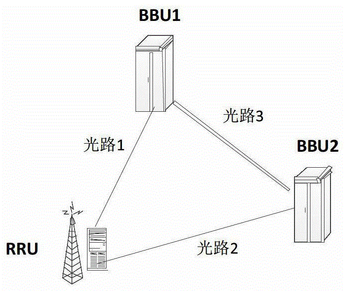
[0028] This embodiment combines figure 2 The shown networking diagram provides a method for implementing service transmission between the RRU and the BBU. Such as figure 2 As shown, the RRU belongs to (that is, connects) to two different BBUs, namely BBU1 and BBU2. BBU1, BBU2 and RRU can be connected through optical cables. Optical path 1 is between the RRU and BBU1; optical path 2 is between the RRU and BBU2.
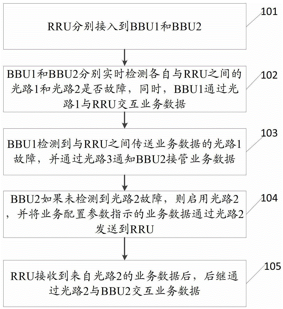
[0029] After the RRU is connected to the BBU1, the BBU1 sends a heartbeat message to the RRU at regular intervals to check whether the optical path 1 is smooth. If the BBU1 does not receive the heartbeat response message fed back by the RRU within the specified time, it is determined that the optical path 1 between the BBU1 and the RRU is faulty;
[0030] Similarly, after the RRU2 is connected to the BBU2, the BBU2 sends a heartbeat message to the RRU at regular intervals to check whether the optical path 2 is smooth. If the BBU2 does not receive the heartbeat r...
Embodiment 2
[0044] In order to facilitate the implementation of the method in Embodiment 1, this embodiment provides a BBU, such as Figure 4 As shown, it includes: a connection module 21 , a fault detection module 22 and a switching module 23 .
[0045] A connection module 21, used for RRU access and establishing a connection with another BBU;
[0046] The fault detection module 22 is used to detect in real time whether the optical path of the optical port between the RRU and the RRU is faulty, and the service data is transmitted through the optical path of the optical port;
[0047] The switching module 23 is used to notify another BBU to take over the service data if the fault detection module 22 detects a fault in the optical path of the optical port channel when the optical path of the optical port channel is used to transmit business data with the RRU; or the switching module 23 It is used to take over the service data of another BBU when receiving the notification of taking over s...
Embodiment 3
[0055] This embodiment provides a system for implementing service transmission between the RRU and the BBU, such as Figure 5 As shown, it includes RRU10 and two BBUs, and the two BBUs are BBU1 and BBU2 respectively;
[0056] RRU10 is used to connect to BBU1 and BBU2 respectively;
[0057] BBU1 is used to detect in real time whether the optical port channel optical path 1 and optical port channel optical path 2 between each of them and RRU10 are faulty, wherein the service data is transmitted through optical port channel optical path 1 between BBU1 and RRU; When the optical port channel optical path 1 that transmits business data fails, notify BBU2 to take over the business data;
[0058] BBU2 is used to detect in real time whether the optical port channel optical path 1 and optical port channel optical path 2 between each and RRU10 are faulty, wherein the service data is transmitted through optical port channel optical path 1 between BBU1 and RRU; and when receiving the noti...
PUM
 Abstract
Description
Claims
Application Information
 - R&D
- Intellectual Property
- Life Sciences
- Materials
- Tech Scout
- Unparalleled Data Quality
- Higher Quality Content
- 60% Fewer Hallucinations
Browse by: Latest US Patents, China's latest patents, Technical Efficacy Thesaurus, Application Domain, Technology Topic, Popular Technical Reports.
© 2025 PatSnap. All rights reserved.Legal|Privacy policy|Modern Slavery Act Transparency Statement|Sitemap|About US| Contact US: help@patsnap.com


