
Cloud computing system, load balancing system, load balancing method and device

A load balancing algorithm and load balancing technology, applied in the field of cloud computing systems, can solve the problems of a large number of VLBs, unfavorable public network IP resources, and reducing cloud computing service costs.

Active Publication Date: 2014-07-02
HUAWEI CLOUD COMPUTING TECH CO LTD
View PDF3 Cites 5 Cited by
  • Summary
  • Abstract
  • Description
  • Claims
  • Application Information

AI Technical Summary

Problems solved by technology

However, the server clusters that implement cloud computing services are relatively large. Correspondingly, the number of VLBs required is relatively large, and many public network IPs need to be occupied, which is not conducive to saving public network IP resources and reducing cloud computing service costs.

Method used


Image

  • Cloud computing system, load balancing system, load balancing method and device
  • Cloud computing system, load balancing system, load balancing method and device
  • Cloud computing system, load balancing system, load balancing method and device

Examples


Embodiment 1

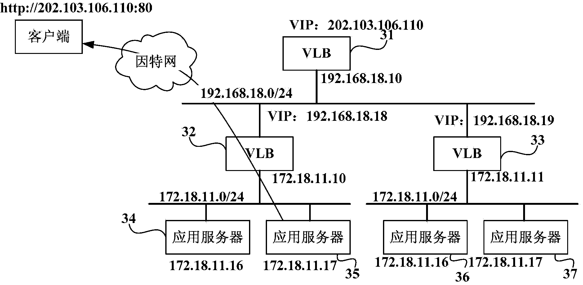
[0049] see image 3 In this embodiment, there are two layers of load balancing. The first layer of load balancing is implemented through the front-end VLB, and the second layer of load balancing is implemented through the back-end VLB.

[0050]There is one front-end VLB: VLB31, which is the upper-level VLB of the back-end VLB; there are two back-end VLBs: VLB32 and VLB33, which are lower-level VLBs of the front-end VLB31.

[0051] The front-end VLB31 is responsible for the distribution of the fourth layer, using the server to directly return the traffic through the router (Direct Server Return, DSR) mode. The back-end VLB is distributed at the seventh layer, and the two-level VLB form is invisible to users.

[0052] When the user obtains the load balancing service, the system creates a front-end VLB for the load balancing service that needs to be obtained, and assigns the corresponding IP address, VIP: 202.103.106.110, to the front-end VLB. The VIP: 202.103.106.110 is the ex...

Embodiment 2

[0061] see Figure 4 , in this embodiment, there are three layers of load balancing, the first layer of load balancing is implemented through the ELB, the second layer of load balancing is implemented through the front-end VLB, and the third layer of load balancing is implemented through the back-end VLB. Accordingly, three levels of distribution are performed for network requests.

[0062] ELB can be deployed on a DNS server, which provides external domain names: www.good.elb.huawei.com .

[0063] There are two front-end VLBs: VLB41 and VLB42, which are upper-level VLBs of the back-end VLBs.

[0064] The domain name returned by the DNS server when the user creates an ELB through the system, accesses the DNS server of the ELB, and the DNS server assigns the VIP of the four-layer distribution VLB that responds to the user's request.

[0065] There are four back-end VLBs: VLB43, VLB44, VLB45 and VLB46, wherein VLB43 and VLB44 are lower-level VLBs of the front-end VLB41, and ...


PUM


Abstract

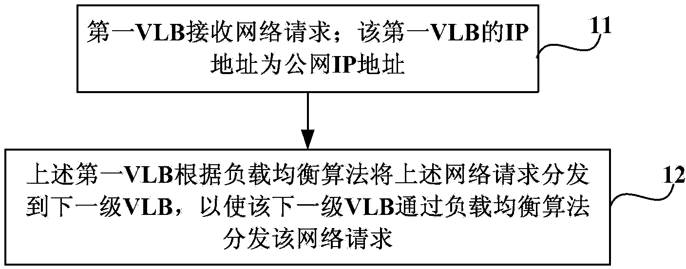
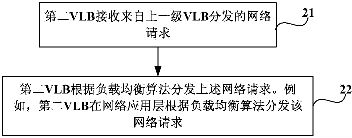
The invention provides a cloud computing system, a load balancing system, a load balancing method and a device. the load balancing method comprises the following steps: a first virtual load balancer VLB receives a network request; the IP address of the first VLB is a public network IP address; and the first VLB issues the network request to a next-level VLB according to a load balancing algorithm such that the next-level VLB issues the network request through the load balancing algorithm. The first VLB performs load balancing on the network request and issues the network request to the next-level VLB such that the network request can once again undergo load balancing and be issued. Thus, only the first VLB occupies the public network IP resource, and the next-level VLB needn't occupy the public network IP and is easy to extend. Therefore, the problem that much more public network IP resources are occupied due to a need of a lot of VLBs and increasing of business requirements in present cloud computing service is solved. Cloud computing service requirements can be met without limit; the public network IP resources are also saved; and costs of the cloud computing service are reduced.

Description

technical field [0001] The invention relates to load balancing technology, in particular to a cloud computing system, a load balancing system, a load balancing method and a device. Background technique [0002] Load balancing is a technology that distributes network requests to available servers in a server cluster according to a load balancing algorithm. Load balancing provides the best possible web experience for web visitors by managing data traffic into server clusters. For example, in cloud computing services, network service requests are distributed to servers with less load for processing through load balancing technology, so as to improve the processing efficiency of network service requests and enable network visitors to obtain a better experience. [0003] Load balancing is divided into hardware load balancing and software load balancing. Hardware load balancing refers to installing a load balancing device between the server and the external network. This kind of...

Claims


Application Information

Patent Timeline
IPC IPC(8): H04L29/08
Inventor 朱国文易明华樊钧
Owner HUAWEI CLOUD COMPUTING TECH CO LTD
Learn More