Ultrasound imaging apparatus, ultrasound imaging method and ultrasound imaging program
An imaging device, ultrasonic technology, applied in ultrasonic/sonic/infrasonic diagnosis, acoustic diagnosis, infrasonic diagnosis, etc., can solve problems such as error vector and boundary recognition reduction
- Summary
- Abstract
- Description
- Claims
- Application Information
AI Technical Summary
Problems solved by technology
Method used
Image
Examples
no. 1 Embodiment approach
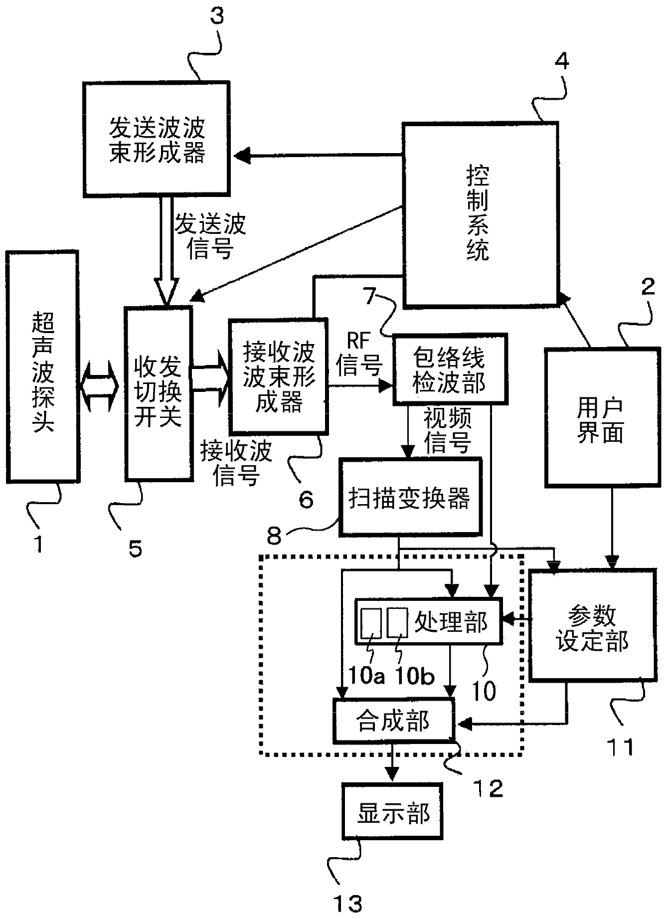
[0054] figure 1 The system configuration of the ultrasonic imaging apparatus of this embodiment is shown. This device has the function of ultrasonic boundary detection. Such as figure 1 As shown, the device includes an ultrasonic probe (probe) 1, a user interface 2, a transmission beamformer 3, a control system 4, a transmission and reception switch 5, a reception beamformer 6, an envelope detection unit 7, a scan conversion device 8, processing unit 10, parameter setting unit 11, synthesis unit 12, and display unit 13.
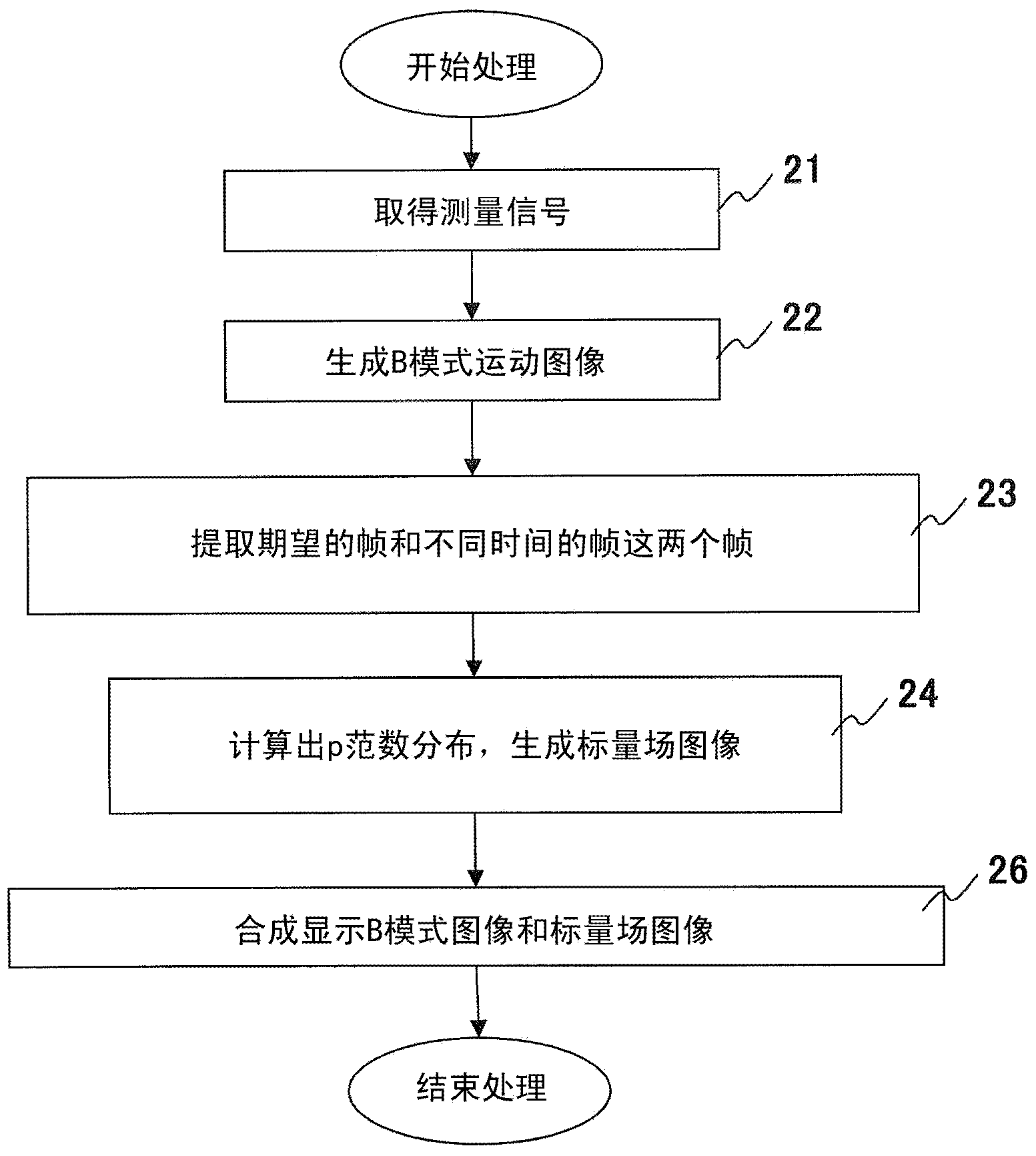
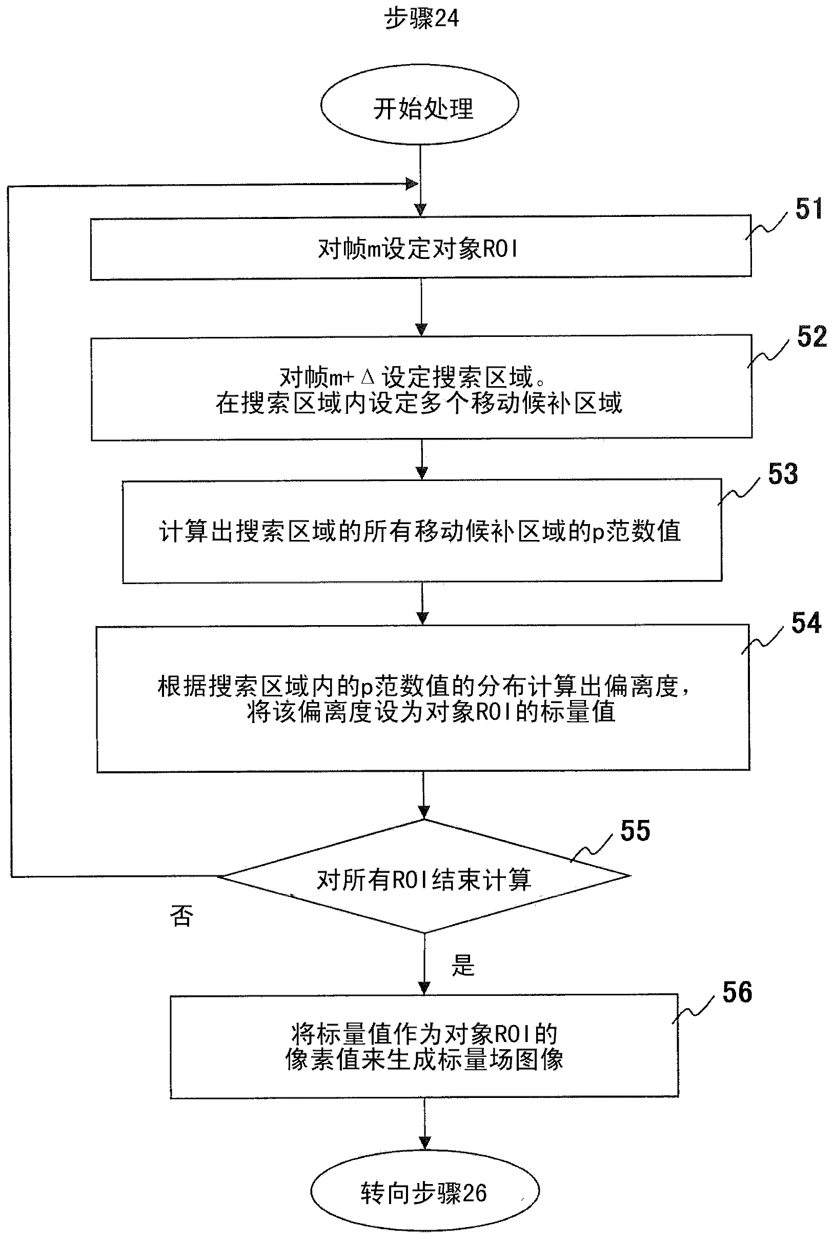
[0055] The ultrasonic probe 1 in which ultrasonic elements are arranged one-dimensionally is a transmitting unit that transmits an ultrasonic beam (ultrasonic pulse) to a living body, and a receiving unit that receives an echo signal (received wave signal) reflected from a living body. Under the control of the control system 4 , the transmission wave beamformer 3 outputs a transmission wave signal having a delay time corresponding to the transmission wave ...
no. 2 Embodiment approach
[0093] In the second embodiment, when a virtual image occurs in the scalar field image obtained in the first embodiment, the virtual image and the like are removed. That is, the reliability of the image region is recognized, and by removing the region with low reliability, virtual images are removed, and the reliability of the entire image is improved. use Figure 9 as well as Figure 10 to illustrate the point.
[0094] Figure 9 (a) is a scalar field image obtained by setting p=1 in the formula (1) as described in the first embodiment, and a virtual image is generated at the boundary portion. Figure 9 (b) is a histogram used in the recognition of the reliability of the image region, Figure 9 (c) is a scalar field image in which the luminance of an image region with low reliability is replaced with a dark color. Figure 10 It is a flowchart showing the operation of the processing unit 10 for removing virtual images.
[0095] First, when the processing unit 10 receives...
no. 3 Embodiment approach
[0099] In the first embodiment, the statistics (deviation degree or variation coefficient) of the p-norm distribution were obtained to generate an image, but in the third embodiment, a tissue-identifiable image was generated from the p-norm distribution using another method. The image of the border. use Figure 11 as well as Figure 12 to describe the processing method.
[0100] In the distribution of the p-norm value in the search area 32, as described in the first embodiment, the candidate area 33 along the boundary of the subject forms a region where the p-norm value becomes smaller along the boundary (trough of the p-norm value). ). Therefore, the distribution of the p-norm value has a characteristic that the value of the candidate region 33 along the boundary shows a smaller value than the value of the candidate region 33 along the direction perpendicular to the boundary. In this embodiment, this feature is used to generate an image.
[0101] Figure 11 The processi...
PUM
 Abstract
Description
Claims
Application Information
 - R&D
- Intellectual Property
- Life Sciences
- Materials
- Tech Scout
- Unparalleled Data Quality
- Higher Quality Content
- 60% Fewer Hallucinations
Browse by: Latest US Patents, China's latest patents, Technical Efficacy Thesaurus, Application Domain, Technology Topic, Popular Technical Reports.
© 2025 PatSnap. All rights reserved.Legal|Privacy policy|Modern Slavery Act Transparency Statement|Sitemap|About US| Contact US: help@patsnap.com


