a building support

A technology for building and frame feet, applied in the field of building supports, can solve problems such as construction safety affecting building quality, high requirements for ground flatness, and easy damage to support components, achieving the effects of good levelness, reduced material consumption, and balanced force.

Active Publication Date: 2015-12-30
浙江升浙建设集团有限公司
View PDF11 Cites 1 Cited by
  • Summary
  • Abstract
  • Description
  • Claims
  • Application Information

AI Technical Summary

Problems solved by technology

The supporting force on the building is basically large, so the single support rod is easy to bend when used, the service life of the support is short, and once the top of the support is tilted, the lifted building will be unevenly stressed and easy to tilt or deviate, or the support If the support fails and damages the upper part of the building, it will seriously affect the quality of the building, and even cause the building to collapse and cause danger
At the same time, when the bracket is fine-tuned, the uneven force on the fine-tuning parts or excessive pressure may cause the bracket parts to be easily damaged, or the uneven force on the bracket will cause the top bracket surface to tilt, which will also affect the quality and construction of the building. security
Moreover, the existing building brackets can only be used on flat ground, which has high requirements on the flatness of the ground, thus greatly reducing the scope of application

Method used


Image

  • a building support
  • a building support
  • a building support

Examples


Embodiment 1

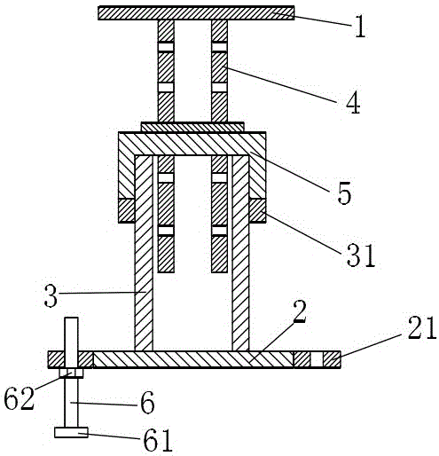
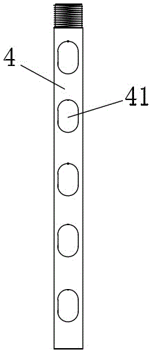
[0043] A kind of construction bracket, comprises upper supporting plate 1 and lower supporting plate 2, and described lower supporting plate 2 is vertically provided with guide tube 3, and described upper supporting plate 1 lower surface is vertically provided with several supporting rods 4, and described supporting The bottom end of the rod 4 is connected with a support sleeve 5 which is sleeved on the guide cylinder 3 and can slide up and down along the guide cylinder 3. The top of the support sleeve 5 is provided with a through hole 43 adapted to the support rod 4. The support The rod 4 is set through the through hole 43, and several through grooves 41 are horizontally arranged on the support rod 4 from top to bottom. 3 is also covered with an adjustment ring 31, the adjustment ring is screwed to the outer surface of the guide cylinder 3, the adjustment ring 31 is against the bottom end of the support sleeve 5, and the outer edge of the lower support plate 2 is evenly distri...

Embodiment 2

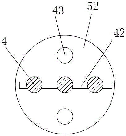
[0049] The difference from the above embodiment is that the support sleeve 5 includes a support plate 52, a support foot 53 and a collar 51 arranged in sequence from top to bottom, the collar 51 abuts on the adjustment ring 31, and the support The rod 4 is inserted into the support plate 52 , the lower end of the positioning insertion strip 42 abuts on the support plate 52 , and the positioning insertion strip 42 passes through one or more support feet 53 . The through holes 43 on the support plate 52 are 6 uniformly distributed around the center of the support plate 52 . The thickness of the support plate is 15cm.

Embodiment 3

[0051] The difference from the above-mentioned embodiment is that there are three through holes 43 evenly distributed on the support plate 52, and there are three support rods. The same, and at least two of the through grooves at the corresponding height positions are located on the same axis. There are a plurality of positioning inserts, and the positioning inserts can be inserted on the three support rods on the same plane, or the positioning inserts can be added on this basis, that is, the additional positioning inserts are inserted on the two support rods. the last slot of a support rod, or insert a positioning insert into the upper slot of the two support rods to ensure that each support rod is pierced with at least two positioning inserts. strip. The support in this arrangement has high strength, can be used to support a supported building with a heavy weight, and the components are not easy to be damaged.


PUM


Abstract

The invention relates to the building field, in particular to a support for a building. The support comprises an upper support plate and a lower support plate; a guide cylinder is arranged on the lower support plate, a plurality of support rods are arranged on the lower surface of the upper support plate, the bottom ends of the support rods are connected with a support sleeve, through holes are formed in the top of the support sleeve, and a plurality of through channels are formed in the support rods; the support further comprises positioning insert strips; an adjusting ring further sleeves the guide cylinder and is propped against the bottom end of the support sleeve; a plurality of connecting plates are evenly distributed at the outer edge of the lower support plate, and threaded holes are vertically formed in the connecting plates; the support further comprises stands adaptive to the threaded holes in the connecting plates; a bracing plate is arranged at the bottom end of each stand, each stand is a stud, and an adjusting nut is fitted on each stand. The support rods are screwed to the upper support plate and then inserted into the guide cylinder, the positioning insert strips are inserted into the through channels, and then the adjusting ring is adjusted for positioning; when the support is used on uneven ground, the stands are arranged in the threaded holes of the connecting plates and then the support is adjusted to a horizontal position by adjusting the nuts.

Description

technical field [0001] The invention relates to the field of construction, in particular to a construction support with high support strength and long service life. Background technique [0002] Most of the existing building supports are supported by a single support rod, and the fine-tuning parts are used for the final jacking. The overall structure is single and the supporting force is limited. The supporting force on the building is basically large, so the single support rod is easy to bend when used, the service life of the support is short, and once the top of the support is tilted, the lifted building will be unevenly stressed and easy to tilt or deviate, or the support If the support fails and damages the upper part of the building, it will seriously affect the quality of the building, and even cause the danger of the building collapsing. At the same time, when the bracket is fine-tuned, the uneven force on the fine-tuning parts or excessive pressure may cause the br...

Claims


Application Information

Patent Timeline
Patent Type & Authority Patents(China)
IPC IPC(8): E04G25/06
Inventor 汤晓明
Owner 浙江升浙建设集团有限公司
Why Eureka
Try Eureka