
Network coding cooperative communication method based on polarization codes

A network coding and cooperative communication technology, applied in the field of network coding cooperative communication based on polar codes, to achieve the effects of avoiding error propagation, optimizing transmission resources, and reducing error rates

Active Publication Date: 2014-07-09
UNIV OF ELECTRONIC SCI & TECH OF CHINA
View PDF1 Cites 36 Cited by
  • Summary
  • Abstract
  • Description
  • Claims
  • Application Information

AI Technical Summary

Problems solved by technology

However, the current existing network coding methods still have certain defects in transmission error rate and transmission stability, and cannot better meet the needs of actual engineering applications.

Method used

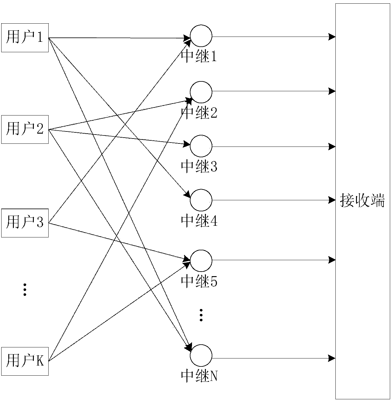

Image

  • Network coding cooperative communication method based on polarization codes
  • Network coding cooperative communication method based on polarization codes
  • Network coding cooperative communication method based on polarization codes

Examples


Embodiment 1

[0034] see figure 2 , for a network with 5 users at the sending end, the process of constructing its network cooperative communication with polar codes is as follows:

[0035] First determine the number of relay nodes to be used, that is, the polar codeword length N, because the number of users is 5, we choose N=2 3 =8 (n=3) to construct a polar code, assuming that the channel is an erasure channel, the erasure probability is ε=1 / 2, and then from the fundamental matrix get the matrix , n=3 in this embodiment, then the corresponding matrix is ​​as follows:

[0036] F ⊗ 3 = 1 0 0 0 0 0 0 0 ...

Embodiment 2

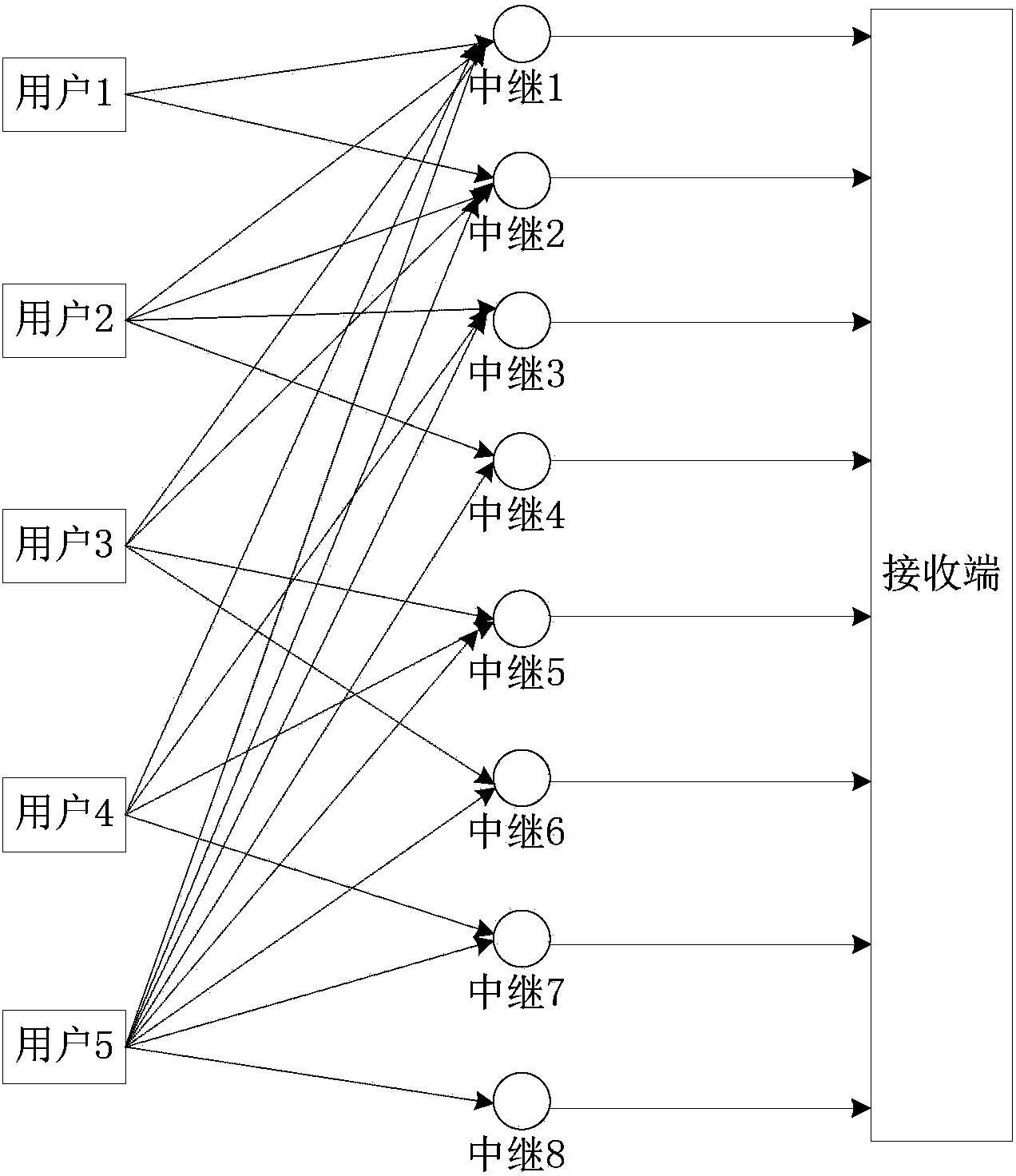
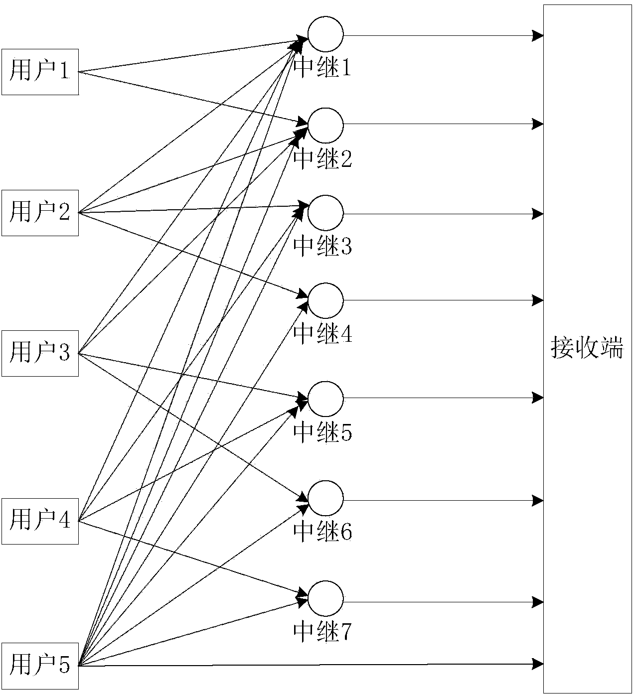
[0041] Current network connections such as Figure 4 As shown, including 3 users and 8 relay nodes (relay 1-8), the corresponding generation matrix obtained based on the polar code construction method of the present invention is , and optimize the transmission resources, in the generation matrix G P In (8,3), because column 5 is the same as column 1, column 6 is the same as column 2, column 7 is the same as column 3, and column 8 is the same as column 4, it can be considered in four groups In (1,5), (6,2), (7,3), and (8,4), only one relay node in each group is reserved, and in this embodiment, relay 1 is selected based on the signal-to-noise ratio , 2, 3, 4, and, because the generator matrix G P In the fourth column of (8,3), only the element in the third row is 1, so the relay 4 is deleted, and the user 3 is directly connected to the receiving end. The optimized network connection is as follows Figure 5 shown. When decoding processing is performed at the receiving end, ...


PUM


Abstract

The invention discloses a network coding cooperative communication method based on polarization codes, and belongs to the technical field of network coding. The method comprises the following steps of constructing a polarization code generation matrix GP, setting polarization code parameters N and K based on the number of relay nodes of the network and the number of users, and constructing a polarization code generation matrix GP again based on N and K, wherein N expresses the code length, K expresses the length of information bits, each column of the matrix GP corresponds to one relay node, and each row of the matrix GP corresponds to one user; receiving information sent by the users through the corresponding relay nodes based on the matrix GP; when the jth column and the ith row of the matrix GP are 1, receiving the information sent by the user corresponding to the ith row through the relay node corresponding to the jth column; carrying out binary domain addition on the received information by the relay nodes, and then sending the information to a receiving end; arranging the N received relay information rj in sequence by the receiving end to form a polarization codeword, and carrying out coding on the polarization codes. The method is used for the network coding, and can reduce transmission error rate and improve the network transmission stability.

Description

technical field [0001] The invention relates to network coding cooperative communication, in particular to a polar code-based network coding cooperative communication method. Background technique [0002] In network research, directed graphs are often used to represent the structure of communication networks. Using the "minimum cut maximum flow" theorem in graph theory, we can know that the maximum flow that this graph (communication network) can transmit is the minimum cut of this graph. . However, the traditional network relay storage and forwarding method cannot meet the realization of this point. In the communication network, network coding technology is used, that is, the technology of encoding and retransmitting information at the relay node. At the receiving end, each destination node can decode the required information through a certain method according to the coding rules, which can greatly Improve the transmission rate of the network, reduce the number of times t...

Claims


Application Information

Patent Timeline
IPC IPC(8): H04L1/00
Inventor 刘强史治平李超
Owner UNIV OF ELECTRONIC SCI & TECH OF CHINA
Learn More