Deformation structure of air vehicle and micro air vehicle

A technology for deforming structures and aircraft, applied in the field of aircraft, can solve the problems that the aircraft cannot optimize the weight and visible space, and can not make full use of the fuselage space, and achieve the effect of optimizing the weight and visible space.

Inactive Publication Date: 2014-07-16
SZ DJI TECH CO LTD
View PDF0 Cites 60 Cited by
  • Summary
  • Abstract
  • Description
  • Claims
  • Application Information

AI Technical Summary

Problems solved by technology

However, since the existing quadrotor aircraft are basically fixed rigid body structures, the space above and on the side of the fuselage cannot be fully utilized. Visual space optimization

Method used


Image

  • Deformation structure of air vehicle and micro air vehicle
  • Deformation structure of air vehicle and micro air vehicle
  • Deformation structure of air vehicle and micro air vehicle

Examples


no. 1 example

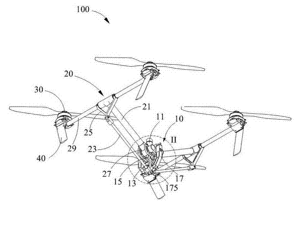
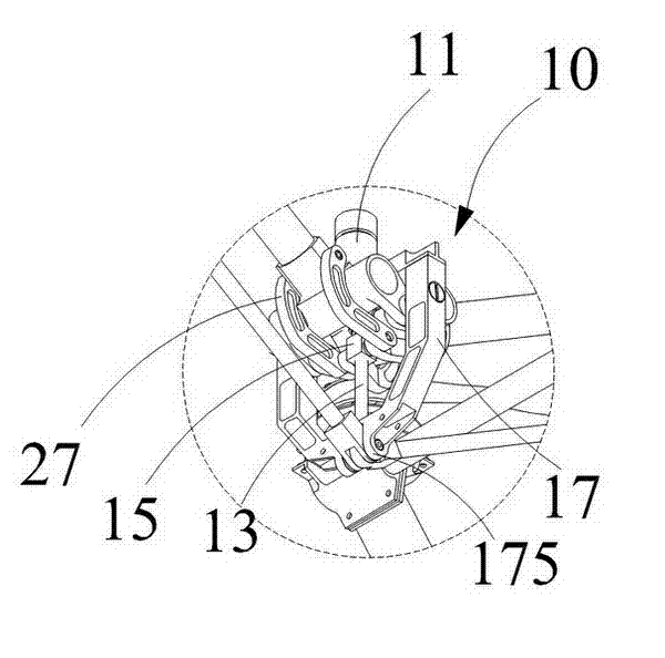
[0038] see Figure 1 to Figure 4 , the first embodiment of the present invention provides a micro air vehicle 100, which is used to carry certain accessories (such as cameras, robotic arms, etc.) wait). In this embodiment, the micro air vehicle 100 is a remote controlled micro air vehicle.

[0039] In this embodiment, the MAV 100 includes a fuselage 10 , two deformable frames 20 , four power units 30 , and four landing supports 40 . The fuselage 10 is connected with a deformable frame 20, and the deformable frame 20 is driven to deform according to a user command or automatically. The power unit 30 is arranged on the frame 20 to drive the micro air vehicle 100 to rise or land. The landing bracket 40 is used to support the MAV 100 on a plane.

[0040] The fuselage 10 includes a driving part 11 , a transmission part and a fixing part 17 . The transmission part is fixedly connected with the driving part 11 , and is driven by the driving part 11 to perform linear reciprocatin...

no. 2 example

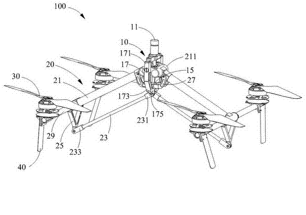
[0058] see Figure 5 to Figure 10 The micro air vehicle 100a provided by the second embodiment of the present invention is basically the same as the micro air vehicle 100 of the first embodiment, except that the main rod 21a and the secondary rod 23a intersect on different planes.

[0059] Specifically, the tie rod 25a in the MAV 100a is roughly in an inverted “concave” shape, so that the tie rod 25a forms two concave corners 251 . The pull rod 25 a is pivotally connected to the cross bar 29 through two end portions, and can rotate relative to the cross bar 29 . In this embodiment, the two concave corners 251 are respectively arranged on two sides of the main rod 21a.

[0060] In order to better match the structural change of the pull rod 25a, the fixing portion 17a is also slightly deformed compared to the first embodiment. Specifically, the fixing portion 17a includes a first side 171a, a second side 173a, a third side 175a, a fourth side 177a and a fifth side 179a connect...

no. 3 example

[0066] see Figure 11 to Figure 14 , the third embodiment of the present invention provides a micro-aircraft 100b that is substantially the same as the first embodiment of the micro-aircraft 100, the difference is that: each frame 20b includes two sub-rods 23b, and the two sub-rods 23b are connected to the main The connecting surface of the rod 21b is surrounded by a triangular prism.

[0067] The pull rod 25b includes a bottom edge 251b and two parallel and opposite side edges 253b, and the two side edges 253b extend vertically upward from the bottom edge 251b. The bottom edge 251b is parallel to the cross bar 29, and two hinge holes (not shown) are provided at both ends, and the two hinge holes are respectively provided on two sides of the main bar 21b. The end of the side 253b is formed with two collars 255b, and the collars 255b are sleeved on the cross bar 29, so that the tie rod 25b can be defined on the cross bar 29, and relative to the Said cross bar 29 rotates. A f...


PUM


Abstract

A deformation structure of an air vehicle. The deformation structure includes: a driving part, a transmission part which is fixedly connected to the driving part, is driven by the driving part, and linearly moves back and forth relative to the driving part, a fixing part which sleeves the transmission part, at least two main rods which are respectively disposed on the two sides of the transmission part, wherein each main rod includes a first bottom part and an opposite first tail part, and the first bottom parts of the at least two main rods are hinged to each other and are limited to one end of the fixing part, wherein the end of the fixing part is in proximity to the driving part, at least two auxiliary rods, wherein each auxiliary rod includes a second bottom part and an opposite second tail part, and the two second bottom parts of the at least two auxiliary rods are hinged to each other and are limited to one end of the fixing part, wherein the end of the fixing part is far away from the driving part, at least two pull rods, wherein one end of each pull rod is connected to the first tail part of one of the main rods and the other end of each pull rod is connected to the second tail part of one of the auxiliary rods, and at least two connecting rods, wherein one end of each connecting rod is hinged to the transmission part and the other end of each connecting rod is hinged to the main rod. The invention also provides a micro air vehicle.

Description

technical field [0001] The invention relates to an aircraft, in particular to a deformation structure of the aircraft and a micro-aircraft using the deformation structure of the aircraft. Background technique [0002] Micro quadrotor aircraft is especially suitable for monitoring, reconnaissance and other tasks in near-ground environments (such as indoors, urban areas and jungles, etc.), and has broad military and civilian prospects. In addition, novel appearance, simple structure, low cost, excellent performance and unique flight control method make it become a new international research hotspot. [0003] When carrying out the overall design of the micro quadrotor aircraft, the following principles need to be followed: light weight, small size, high speed, low energy consumption and low cost. However, there are constraints and contradictions between these principles. For example, when the weight of an aircraft is the same, its size is inversely proportional to its speed an...

Claims


Application Information

Patent Timeline
Patent Type & Authority Applications(China)
IPC IPC(8): B64C27/02
CPCB64C37/00B64U2101/30B64U2201/20B64U30/293B64U10/14A63H27/12B64C25/12B64C25/32B64C39/028B64U10/10B64U10/13B64U30/20B64U50/13B64U50/19B64U2201/00B64C1/00B64C27/08B64C39/024B64C1/063G05D1/042B64D47/00B64D47/08B64C1/061B64C2025/325
Inventor 汪滔赵涛杜昊王铭熙
Owner SZ DJI TECH CO LTD
Why Eureka
Try Eureka