
Method and apparatus for channel prediction in wireless networks

Inactive Publication Date: 2005-10-13
LUCENT TECH INC
View PDF9 Cites 52 Cited by
  • Summary
  • Abstract
  • Description
  • Claims
  • Application Information

AI Technical Summary

Benefits of technology

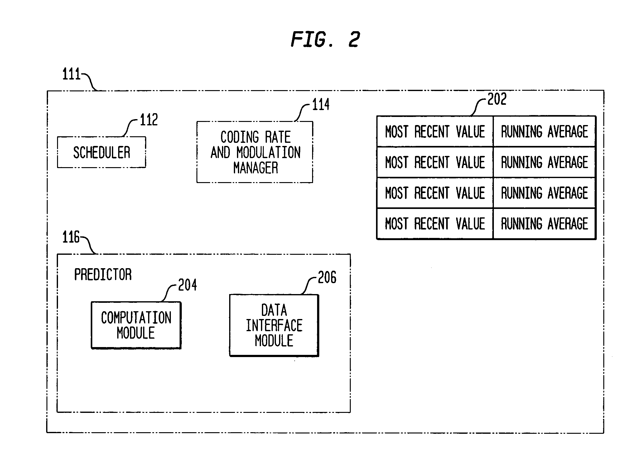
[0009] In order to schedule transmission for efficient throughput and to manage operations necessary for transmission, such as encoding of data and setting of data units that can be transmitted during a timeslot, the base station makes predictions about the channel condition that will be experienced by each mobile unit when transmission is performed. Transmission by the base station to a mobile unit will be separated by some lag from the most recent channel condition information available for that mobile unit. For a slowly changing channel, the best prediction performance is provided by specific channel condition prediction based on recent channel condition values, while in a rapidly changing channel, better prediction performance is provided by taking the mean of the sequence of channel condition values that occurred over time. When making channel predictions, therefore, the base station computes the mean of the sequence of channel condition values and computes the channel condition prediction in such a way as to assign a greater weight to specific predictions when a channel is changing slowly and a greater weight to the mean value of the overall sequence when a channel is changing rapidly. The weight is computed based on the gradient of the prediction error with respect to the weight.

Problems solved by technology

In addition, it may not be desired to transmit to a particular mobile unit at the exact moment that information relating to the channel condition is received.
In a typical wireless environment, a channel predictor encounters a potentially wide range of fading and path loss scenarios.
In cases where fading and other changes are occurring rapidly, channel quality prediction beyond the short term mean is difficult.

Method used


Image

  • Method and apparatus for channel prediction in wireless networks
  • Method and apparatus for channel prediction in wireless networks
  • Method and apparatus for channel prediction in wireless networks

Examples


Embodiment Construction

[0016] The present invention will be described more fully hereinafter with reference to the accompanying drawings, in which several presently preferred embodiments of the invention are shown. This invention may, however, be embodied in various forms and should not be construed as limited to the embodiments set forth herein. Rather, these embodiments are provided so that this disclosure will be thorough and complete, and will fully convey the scope of the invention to those skilled in the art.

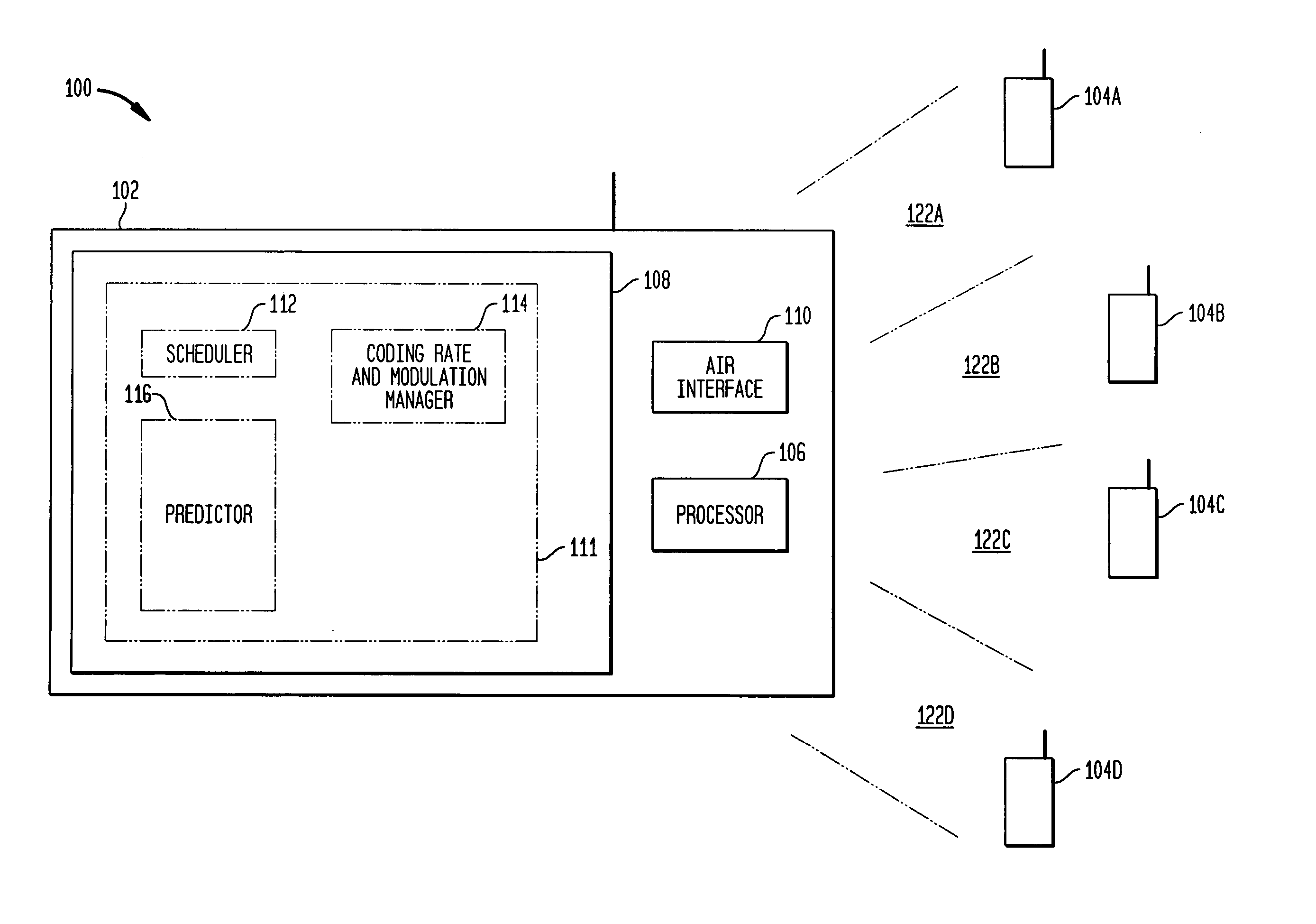
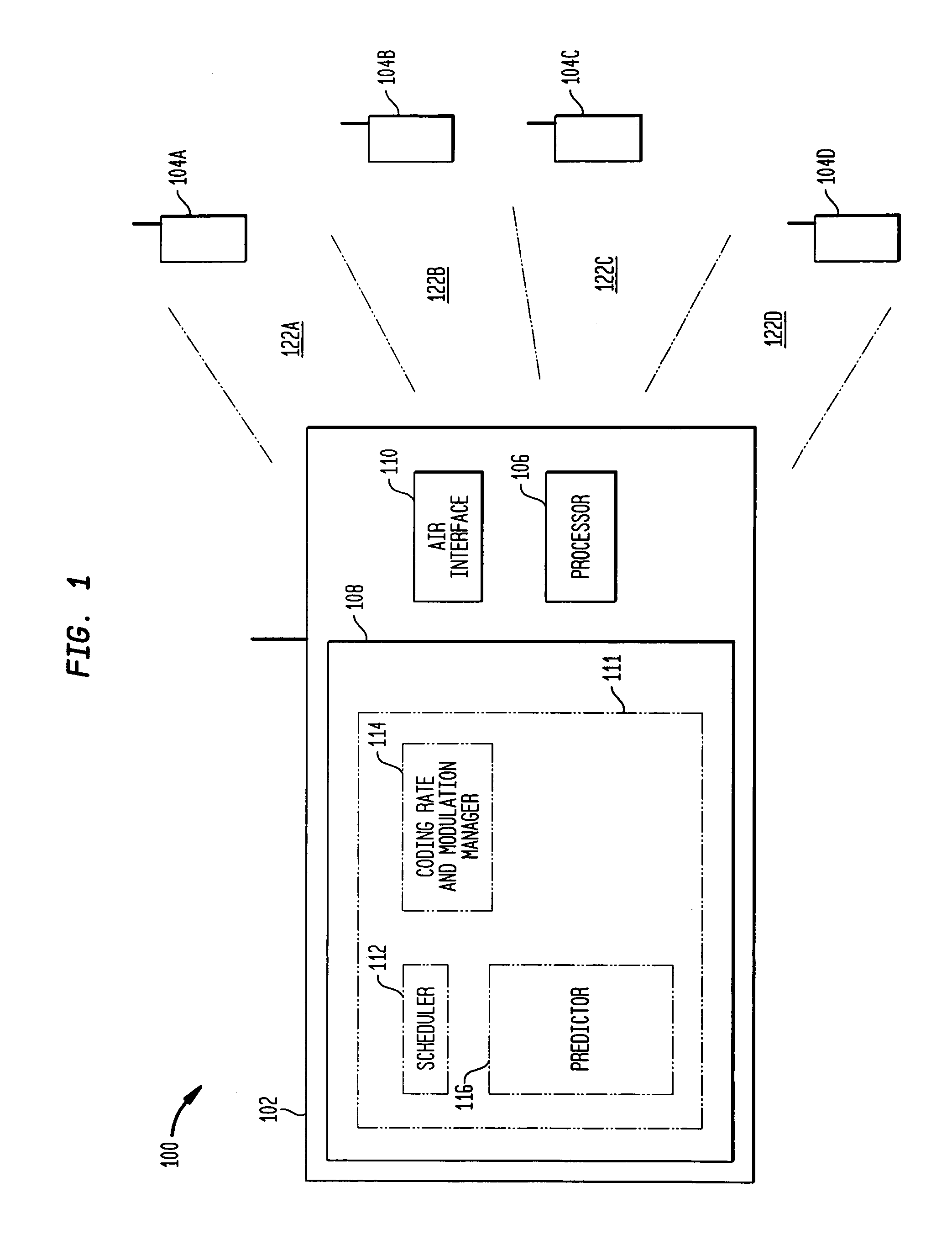
[0017]FIG. 1 illustrates a wireless system 100, comprising a plurality of base stations such as the base station 102, with each of the base stations serving a plurality of mobile units such as the mobile units 104A-104D. For simplicity of illustration, only a single base station 102 and four mobile units 104A-104D are illustrated here, but it will be recognized that many base stations and many mobile units may be supported.

[0018] The base station 102 suitably includes a processor 106 and memor...


PUM


Abstract

Techniques and systems for channel prediction in wireless networks. A base station receives a succession of channel indicators from each of a plurality of mobile units, each channel indicator being received from each mobile unit once per timeslot. A channel predictor uses the channel indicators to generate a channel condition prediction for each mobile unit, the channel condition prediction being based on a balanced estimate using the most recent channel condition indicator and the mean of the succession of channel indicators. A weight is computed based on a gradient of the succession channel indicator values and used to assign relative emphasis to the most recent channel condition indicator and the mean channel condition indicator in order to give greater emphasis to the most recent indicator during slowly changing conditions and greater emphasis to the mean indicator during rapidly changing conditions.

Description

FIELD OF THE INVENTION [0001] The present invention relates generally to improved systems and methods for operation of wireless networks. More particularly, the invention relates to advantageous techniques for predicting channel qualities and the use of predictions of channel qualities in operations such as rate selection and transmission scheduling. BACKGROUND OF THE INVENTION [0002] As wireless services continue to develop, data communication is becoming a more and more important part of the services. Important elements and services needed for wireless data communication include channel estimation and prediction, scheduling, coding rate and modulation selection and hybrid automatic repeat request (HARQ). [0003] Of particular interest is channel prediction, because channel prediction is important for use in scheduling. A base station chooses which mobile unit to serve based in significant part on the quality of the channel as experienced by the mobile units. Typically, transmission...

Claims


Application Information

Patent Timeline
IPC IPC(8): H04W72/08
CPCH04W24/00H04W72/085H04W72/0413H04L1/0026H04W72/21H04W72/542
Inventor BORST, SIMON C.GUPTA, PIYUSHWHITING, PHILIP A.
Owner LUCENT TECH INC
Learn More