
A roller reducer loader

A technology of drum reducer and loader, which is applied in the testing of machine/structural components, instruments, measuring devices, etc., can solve the problem that the drum reducer cannot be connected to the magnetic powder brake for loading test, and achieve the effect of improving the test accuracy.

Active Publication Date: 2016-04-06
JIANGSU TAILONG MACHINERY GRP CO CO LTD
View PDF7 Cites 0 Cited by
  • Summary
  • Abstract
  • Description
  • Claims
  • Application Information

AI Technical Summary

Problems solved by technology

[0003] In order to solve the problem that the roller reducer cannot be connected with the magnetic powder brake for loading test in the prior art, the purpose of the utility model is to provide a roller reducer loader

Method used


Image

  • A roller reducer loader
  • A roller reducer loader

Examples


Embodiment Construction

[0017] Below in conjunction with accompanying drawing, the specific embodiment of the present invention is described in further detail:

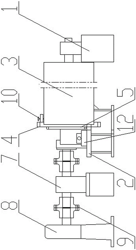
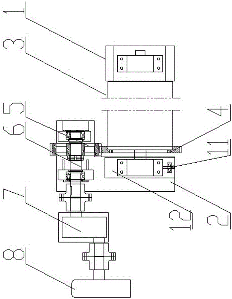
[0018] As shown in the figure, a roller reducer loader includes a support 1, a bracket 2, a roller reducer 3, a large gear 4, a pinion 5, a bridge shaft 6, a reducer 7, a magnetic powder brake 8, and a coupling 9 , Adjusting screw 10, limit screw 11 and pad 12. The hanging foot on the right side of the roller reducer 3 is fixedly supported on the support 1, and the hanging foot on the left side of the roller reducer 3 is supported on the bracket 2 through the pad 12, and the pad 12 is fixed on the bracket 2 through the positioning pin The top surface of the pad 12 is provided with a T-shaped groove, and the left hanging foot is in a sliding state in the T-shaped groove; the end surface of the roller reducer 3 near the side of the bracket 2 is connected with a large gear 4 through a threaded piece , the back of the big gear 4 is provided wit...


PUM


Abstract

The invention relates to a roller speed reducer loader. A hitching leg at one end of a roller speed reducer is fixedly supported by a supporting base, a hitching leg at the other end of the roller speed reducer is supported by a support, a large gear is connected to the end face at the end, close to a machine frame, of the roller speed reducer, a gap bridge shaft parallel to a rotation shaft of the roller speed reducer is further arranged on the support, one end of the gap bridge shaft is connected with a small gear, and the small gear is meshed with the large gear. When the roller speed reducer loader is tested and used, a magnetic powder brake is set according to loading rated performance parameters of the roller speed reducer, and torque is sequentially transmitted to the magnetic powder brake through the roller speed reducer; when the actual working loading torque of the roller speed reducer reaches a rated loading value, the loading torque is transmitted to the magnetic powder brake to enable the magnetic powder brake to rotate; conversely, the loading torque is transmitted to the magnetic powder brake, rotation torque of the magnetic powder brake is not sufficient, and the magnetic powder brake cannot rotate normally. Thus, rated performance loading testing of the roller speed reducer is realized.

Description

technical field [0001] The invention relates to a reducer testing device, in particular to a roller reducer loader. Background technique [0002] Drum reducer is a new type of drive device that puts the motor and reducer inside the drum body. It is used as the power of belt conveyors and hoisting equipment, and is widely used in mining, metallurgy, chemical industry, coal, building materials, electricity, food and transportation. Transportation and other departments. The drum reducer has no output shaft, so it cannot be connected with the magnetic powder brake for loading test. Contents of the invention [0003] In order to solve the problem in the prior art that the roller reducer cannot be connected with the magnetic powder brake for loading test, the purpose of this utility model is to provide a roller reducer loader. [0004] To achieve the above object, the technical solution of the present invention is: [0005] A loader for a roller reducer, including a bracket, ...

Claims


Application Information

Patent Timeline
Patent Type & Authority Patents(China)
IPC IPC(8): G01M99/00
Inventor 阚军荣殷爱国张介禄
Owner JIANGSU TAILONG MACHINERY GRP CO CO LTD
Learn More