An automatic gas pressurization device

A technology of gas pressurization and equipment, applied in the direction of electric fluid pressure control, etc., can solve the problems of not being able to use multiple pressures for filling, low safety factor, waste of energy, etc., to achieve easy observation and operation, safe and reliable quality , to ensure the effect of supercharging speed

Active Publication Date: 2017-04-19
海德利森(天津)检测设备有限公司
View PDF5 Cites 0 Cited by
  • Summary
  • Abstract
  • Description
  • Claims
  • Application Information

AI Technical Summary

Problems solved by technology

[0003] Most of the existing reactors are filled with electric-driven membrane presses. There are problems and shortcomings in the filling of electric-driven membrane presses: single function, complex operation, large volume and weight, low degree of automation, and only manual filling; Directly driven by the motor, the cycle speed is not adjustable, the flow rate is not variable, and it cannot be used for multiple pressure filling; the inlet pressure range is narrow, and when the inlet pressure is high, it generally needs a decompression device to decompress, which is a waste of energy. It belongs to blind filling and is safe. The coefficient is not high; it needs to be equipped with additional power and cooling equipment, the cost is high, and it is easy to cause pollution
Reasons for existence: limitations of electric membrane press technology; relatively little domestic investment and research in this field, and insufficient attention to multifunctional, automated systems, and environmentally friendly products

Method used


Image

  • An automatic gas pressurization device
  • An automatic gas pressurization device
  • An automatic gas pressurization device

Examples


Embodiment Construction

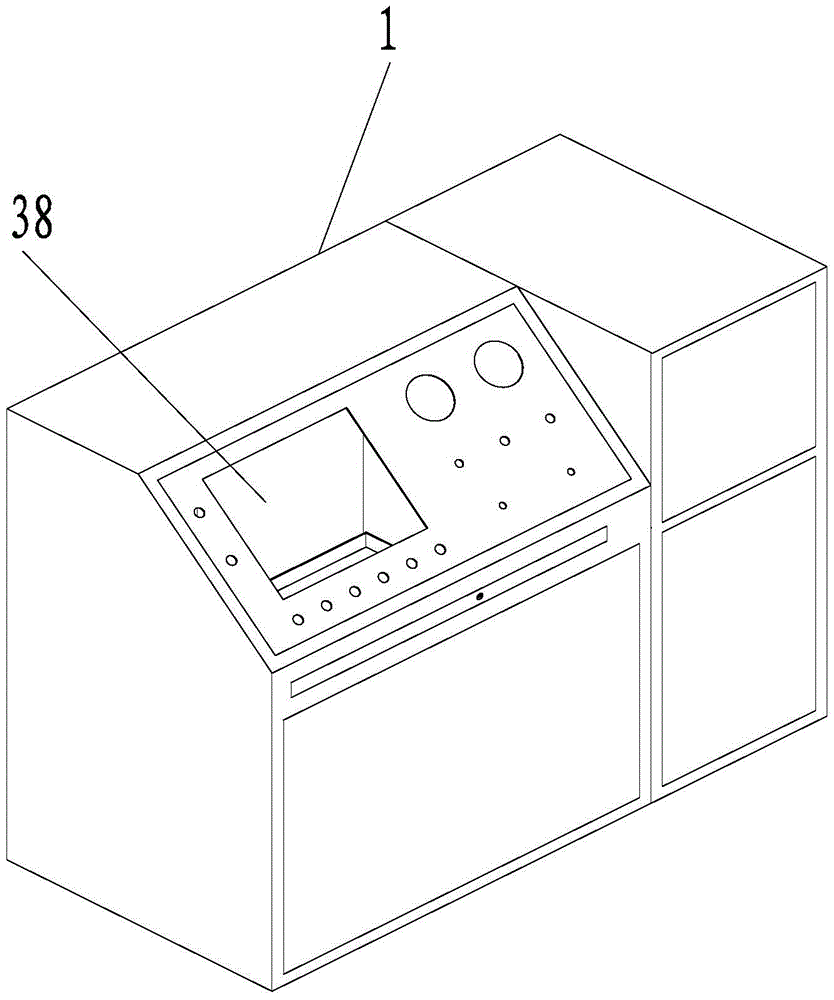
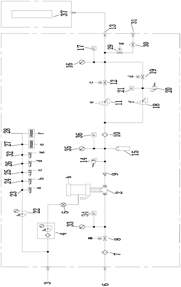
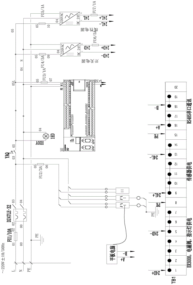
[0025] Such as Figure 1-5 As shown, an automatic gas pressurization device described in the embodiment of the present invention includes a cabinet 1, and the cabinet 1 is provided with a control unit, a pipeline unit and a power supply, and the power supply device in the control unit and the pipeline unit All are connected to the power supply, the control unit includes a host computer and a PLC controller, and the host computer is connected to the PLC controller through a communication cable; the pipeline unit includes a driving gas input pipeline, a gas input pipeline , a gas-driven booster pump 2 and a high-pressure gas output pipeline; the driving gas input pipeline is sequentially connected in series with a driving gas input source 3, a filter pressure reducing valve 4, and a speed regulating valve 5, and the output end of the speed regulating valve 5 It is connected with the driving gas input interface of the gas-driven booster pump 2; the gas input pipeline is sequentia...


PUM


Abstract

The invention relates to an automatic gas pressurizing device which comprises a device cabinet. A control unit, a pipe unit and a power source are arranged in the device cabinet. The control unit comprises an upper computer and a PLC, and the upper computer is connected with the PLC through a communication cable. The pipe unit comprises a driving gas input pipe, a gas input pipe, a booster pump and a high-pressure gas output pipe, a second branch is connected between the output end of a driving gas input source and a filter reducing valve, digital ports of the PLC are connected with a first electromagnetic valve, a second electromagnetic valve, a third electromagnetic valve and a fourth electromagnetic valve respectively, and analog quantity output ports of the PLC are connected with a first electrical proportional valve and a second electrical proportional valve respectively. The automatic gas pressurizing device has the advantages that the gas driven booster pump is adopted, the pressurizing speed is guaranteed, the working time of the booster pump is guaranteed, and the service life of the booster pump is long; mechanical-electrical integration design is adopted, and the automatic gas pressurizing device is small in size, light in weight and convenient to move; the driving gas electrical proportional valves and the gas control reducing valve are allocated, the driving gas output pressure and the driving gas pressurizing speed can be controlled, and therefore the gas driven booster pump is controlled to slowly and stably carry out pressurizing to enable the test pressure to be achieved.

Description

technical field [0001] The invention relates to an automatic gas pressurization device. Background technique [0002] The reactor belongs to the category of pressure vessel and is a special equipment that needs to accept the safety supervision of government departments. It is an industrial product comprehensively developed in a number of new materials, new technologies, and new processes. At the same time, it is a catalyst for many new industries and is widely used. The performance requirements of high-pressure reactors in all aspects far exceed those of conventional industrial application reactors. [0003] Most of the existing reactors are filled with electric-driven membrane presses. There are problems and shortcomings in the filling of electric-driven membrane presses: single function, complex operation, large volume and weight, low degree of automation, and only manual filling; Directly driven by the motor, the cycle speed is not adjustable, the flow rate is not varia...

Claims


Application Information

Patent Timeline
Patent Type & Authority Patents(China)
IPC IPC(8): G05D16/20
Inventor 韩武林
Owner 海德利森(天津)检测设备有限公司
Why Eureka
Try Eureka