Automatic reloading system

An automatic and material technology, applied in the direction of thin material processing, coiling strips, transportation and packaging, etc., can solve the problems of low production efficiency, short normal working hours of the host, and failure of the host to operate, so as to improve production efficiency and ensure normal operation. Working time and improvement of molding efficiency

Inactive Publication Date: 2016-06-22
SAFE RUN & HISCENT MACHINERY SUZHOU
View PDF6 Cites 2 Cited by
  • Summary
  • Abstract
  • Description
  • Claims
  • Application Information

AI Technical Summary

Problems solved by technology

[0002] The feeding method of the existing tire building machine: After each roll of material is used up, the workers change a roll of new material. During the material change process, the main machine cannot run and needs to stop to wait for new material. The new material passes through the conveying channel from the uncoiler It also takes enough time to be transported to the position of the main machine, and the material roll needs to be replaced many times during the working cycle, which makes the normal working time of the whole main machine short and makes the entire production efficiency low

Method used


Image

  • Automatic reloading system
  • Automatic reloading system

Examples


specific Embodiment 1

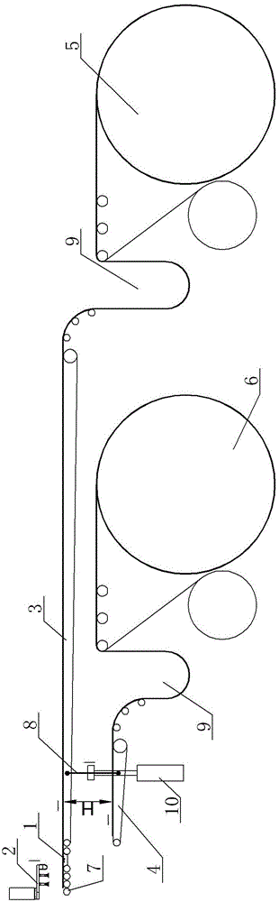
[0018] Specific embodiment one, see figure 1 : the No. 1 material conveyor belt 3 is located directly above the No. 2 material conveyor belt 4, and the height difference is H; the No. 1 guide uncoiling mechanism 5 is located behind the No. 2 guide uncoil mechanism 6; Connecting fasteners 8 are arranged between the output ends of the No. material conveying belt 3, and a cylinder 10 that can be vertically lifted is connected outside the fastening connector 8;

[0019] The driving stroke driven by the vertical lifting cylinder 10 is the height difference H of the two material conveyor belts, ensuring that when the No. 1 material conveyor belt 3 is short of material, the fast position of the No. 2 material conveyor belt 4 reaches the original position of the No. 1 material conveyor belt 3.

specific Embodiment 2

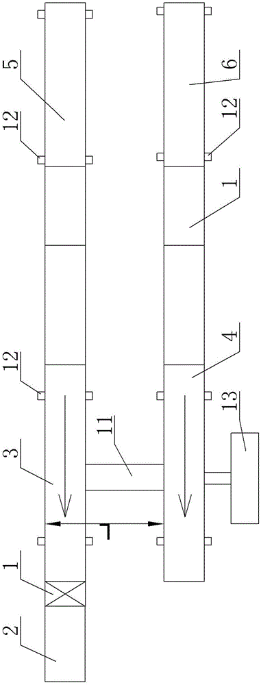
[0020] Specific embodiment two, see figure 2 : No. 1 material conveyor belt 3 and No. 2 material conveyor belt 4 are arranged in parallel on the same horizontal plane, and the horizontal distance between them is L. No. 1 guide uncoiling mechanism 5 is located directly behind the input end of No. 1 material conveyor belt 3. The uncoiling mechanism 6 is located directly behind the input end of the No. 2 material conveyor belt 4, and a connecting rod 11 is arranged between the No. 1 material conveyor belt 3 and the No. 2 material conveyor belt 4. The bottom is provided with a moving structure 12, and one side of the No. 2 material conveyor belt 4 is provided with a horizontal drive cylinder 13. The output end of the horizontal drive cylinder 13 is fixed on the side of the No. 2 material conveyor belt 4. The horizontal drive cylinder 13 The driving stroke is the horizontal distance L between the two material conveyor belts, ensuring that when the No. 1 material conveyor belt 3 is...


PUM


Abstract

The invention provides an automatic material changing system, after one roll of material is used up, the main machine does not need to stop, and the other roll of material can continuously supply materials, so as to ensure the uninterrupted operation of the main machine, improve the overall molding efficiency, and ensure the stability of the main machine. Normal working hours, increased productivity. It includes two sets of feeding structures, the two sets of feeding structures correspond to one main engine, while one set of feeding mechanisms in the two sets of feeding structures feeds the main engine, the other set of feeding structures completes loading and unloading and enters the state of waiting for feeding , the two groups of feeding structures switch each other to complete the continuous feeding of the host.

Description

technical field [0001] The invention relates to the technical field of material conveying of tire building machines, in particular to an automatic material changing system. Background technique [0002] The feeding method of the existing tire building machine: After each roll of material is used up, the workers change a roll of new material. During the material change process, the main machine cannot run and needs to stop to wait for new material. The new material passes through the conveying channel from the uncoiler It also takes enough time to be transported to the position of the main machine, and the material roll needs to be replaced many times in the working cycle, which makes the normal working time of the whole main machine short and makes the efficiency of the whole production low. Contents of the invention [0003] In view of the above problems, the present invention provides an automatic material changing system. After one roll of material is used up, the main ...

Claims


Application Information

Patent Timeline
Patent Type & Authority Applications(China)
IPC IPC(8): B65H19/18
CPCB65H19/1836B65H2801/93
Inventor 李志军
Owner SAFE RUN & HISCENT MACHINERY SUZHOU
Why Eureka
Try Eureka