
Anti-misoperation protector

A protection device and anti-misoperation technology, which is applied in the direction of electrical components, electric switches, circuits, etc.

Inactive Publication Date: 2014-07-16
宝鸡市航宇光电显示技术开发有限责任公司
View PDF4 Cites 5 Cited by
  • Summary
  • Abstract
  • Description
  • Claims
  • Application Information

AI Technical Summary

Problems solved by technology

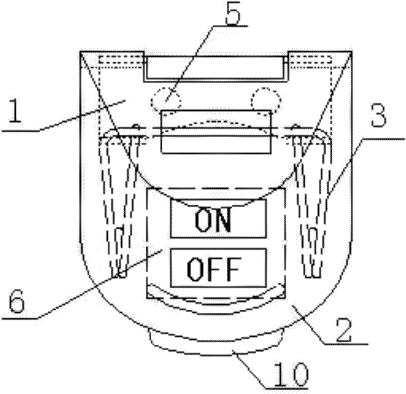
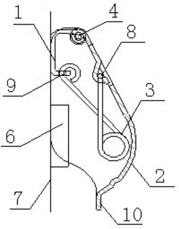
[0003] The purpose of the present invention is to design an anti-misoperation protection device to solve the problem of triggering the crew when they encounter adjacent buttons during operation, and to prevent misoperation of some important buttons.

Method used


Image

  • Anti-misoperation protector
  • Anti-misoperation protector

Examples


Embodiment Construction

[0011] Such as figure 1 , 2 Specific embodiments of the invention are given. The anti-misoperation protection device has a protective cover 2 covering the protected key 6, one end of the protective cover 2 is connected with the base 1 through a shaft 4, and a return spring 3 is installed between the protective cover 2 and the base 1. The middle parts on both sides of the return spring 3 are stuck in the card slot 8 in the middle of the cover 2, and the two ends of the return spring 3 are bent and hung on the spring holes 9 on the base 1, and the middle of the return spring 3 is installed through the screw on the base. The hole 5 is installed and fixed on the panel 7 .

[0012] The surface of the protective cover 2 has a red matte paint as a surface coating, and a protruding part 10 is formed at the end.

[0013] Such as figure 1 As shown, the protection device of the present invention is composed of a base 1, a protective cover 2, a return spring 3, and a shaft 4. The base...


PUM


Abstract

The invention relates to an anti-misoperation protector so as to solve the problem that when flight crews carry out operation, adjacent keys are touched and triggered, and protect certain important keys against misoperation. The anti-misoperation protector is provided with a protecting hood covering protected keys, one end of the protecting hood is connected with a base through a shaft, and reset springs are installed between the protecting hood and the base. The anti-misoperation protector has the advantages that when the flight crews carry out operation, adjacent keys are touched and triggered, and certain important keys are protected against misoperation.

Description

technical field [0001] The invention relates to a protection device for preventing crew members from misoperation. Background technique [0002] There are a lot of buttons on the aircraft, and it happens that the crew encounters the buttons that should not be operated. In order to prevent the adjacent buttons from being triggered by mistake, some important buttons must be prevented from misoperation. Contents of the invention [0003] The object of the present invention is to design an anti-misoperation protection device to solve the problem of triggering the crew members when they encounter adjacent buttons when operating, and to prevent misoperation of some important buttons. [0004] Specifically, the anti-misoperation protection device has a protective cover covering the protected key, one end of the protective cover is connected with the base through a shaft, and a return spring is installed between the protective cover bases. [0005] Advantage of the present invent...

Claims


Application Information

Patent Timeline
Patent Type & Authority Applications(China)
IPC IPC(8): H01H9/02
Inventor 张九毜
Owner 宝鸡市航宇光电显示技术开发有限责任公司
Learn More