
Terminal Cluster Of Electric Connector And Electric Connector Thereof

A technology of electrical connectors and terminals, which is applied to parts, connections, circuits, etc. of connecting devices, can solve the problems of poor transmission efficiency and crosstalk interference of electrical connectors, and achieve the goal of improving poor transmission efficiency and avoiding crosstalk interference Effect

Active Publication Date: 2014-07-16
STARCONN ELECTRONICS SU ZHOU CO LTD
View PDF4 Cites 29 Cited by
  • Summary
  • Abstract
  • Description
  • Claims
  • Application Information

AI Technical Summary

Problems solved by technology

[0008] The main purpose of the present invention is to provide a terminal cluster of an electrical connector, which can improve the shortcomings of conventional electrical connectors such as poor transmission efficiency and crosstalk interference by integrating the configuration of the terminal cluster

Method used


Image

  • Terminal Cluster Of Electric Connector And Electric Connector Thereof
  • Terminal Cluster Of Electric Connector And Electric Connector Thereof
  • Terminal Cluster Of Electric Connector And Electric Connector Thereof

Examples


Embodiment Construction

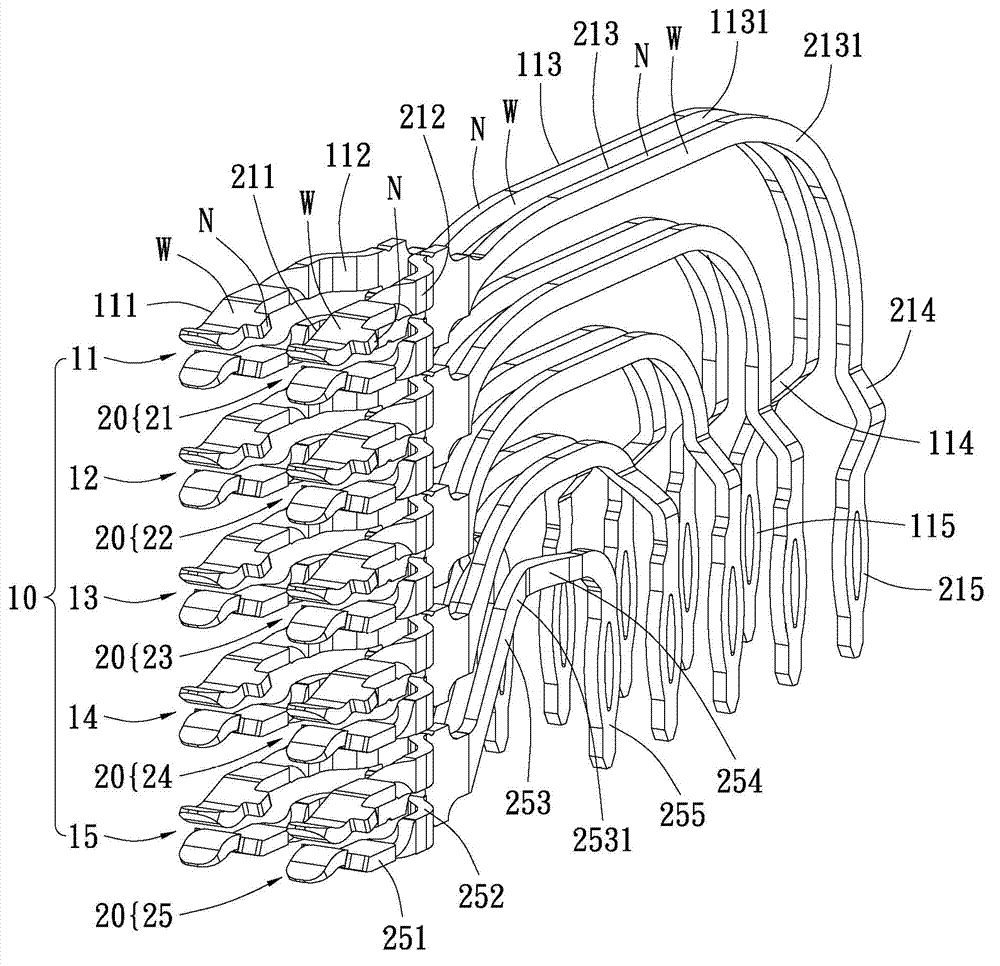
[0103] see Figure 2A , Figure 2B and Figure 2C As shown, the present invention provides a terminal cluster CL of an electrical connector, which is used to form on a shell surface (number omitted), and is used to reduce the external crosstalk between the terminals of the electrical connector itself and the terminals of the electrical connector interference.

[0104] terminal cluster CL as Figure 2A As shown, in a preferred example but not limited thereto, it is composed of a first terminal group 10 and a second terminal group 20 arranged side by side, and each terminal group includes 5 terminals from top to bottom The first terminals are respectively the first terminals ( 11 , 12 , 13 , 14 and 15 ) and the second terminals ( 21 , 22 , 23 , 24 and 25 ), thus defining a 2×5 terminal group to form the terminal array area T. terminal cluster CL as Figure 2A and Figure 2B As shown, it can be covered by a dielectric shell I to form an electrical connector, and the dielect...


PUM


Abstract

The invention provides a terminal cluster of an electric connector and the electric connector thereof. The terminal cluster of the electric connector comprises a terminal array area which is used for forming on a housing surface and furthermore the terminal array area comprises a plurality of longitudinally and successively arranged terminal rows in parallel, wherein each terminal row comprises at least one signal transmitting unit and at least one grounding unit. The at least one signal transmitting unit and the at least one grounding unit are transversely and alternately arranged, thereby reducing crosstalk interference of the terminal and crosstalk interference to outside and simultaneously reducing number of grounding elements required in a unit area and increasing proportion of signal transmitting terminals so as to improve transmission efficiency.

Description

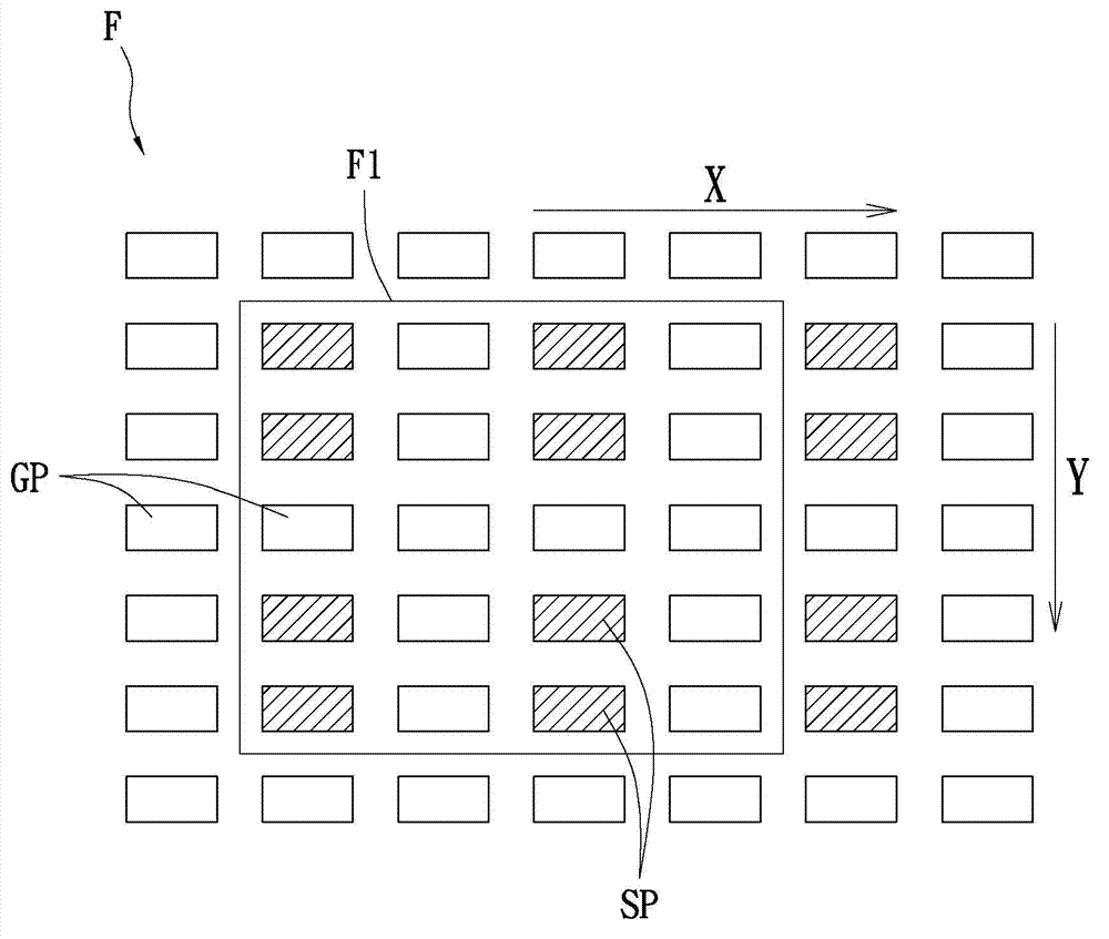
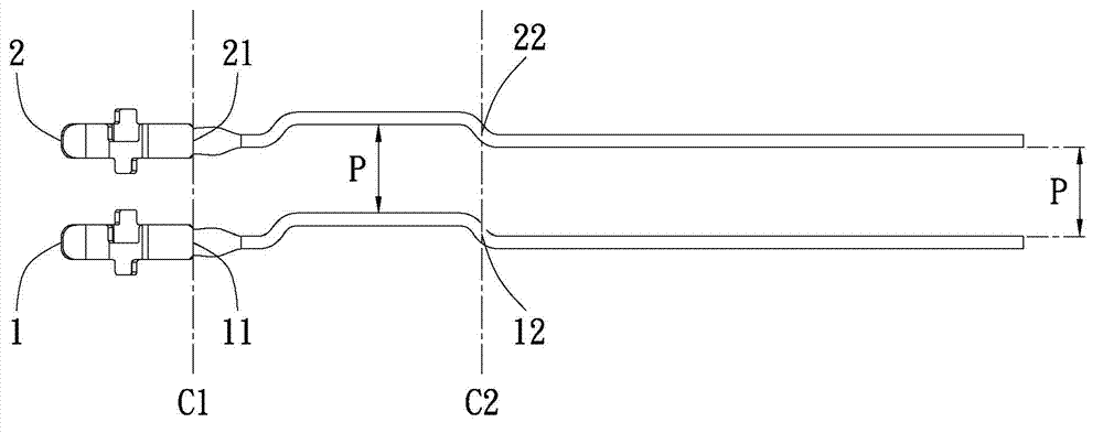
technical field [0001] The invention relates to a terminal cluster of an electrical connector and an electrical connector, in particular to a terminal cluster and an electrical connector of an electrical connector related to an integrated terminal array and structure. Background technique [0002] The configuration of the existing electrical connector on its terminal cluster mainly includes two aspects, one is the array arrangement of the electrical contacts at the terminal end and the structure of the terminal body, so as to achieve an electrical connector with good transmission quality and low crosstalk interference , the configuration on its terminal cluster is extremely important. [0003] However see Figure 1A and Figure 1B As shown, the two figures involve most of the appearance of an electrical connector terminal cluster, Figure 1A A conventional electrical contact array F is shown, which is arranged in a 7x7 pattern in the vertical direction Y and horizontal dire...

Claims


Application Information

Patent Timeline
IPC IPC(8): H01R13/6471H01R13/02
Inventor 包中南林钰雄黄圣翔柯宇丰
Owner STARCONN ELECTRONICS SU ZHOU CO LTD
Learn More