A crane component and its linkage connection device

A connecting device and crane technology, applied in the direction of traveling mechanism, transportation and packaging, load hanging components, etc., can solve the problem of low connection efficiency, achieve the effect of improving connection efficiency and realizing automatic linkage connection

Active Publication Date: 2016-03-23
北京云中未来科技有限公司
View PDF5 Cites 0 Cited by
  • Summary
  • Abstract
  • Description
  • Claims
  • Application Information

AI Technical Summary

Problems solved by technology

[0004] The purpose of the present invention is to provide a linkage connection device to solve the problem in the prior art that the connection efficiency is low due to manual installation of bolts or pins when the crane needs to be linked; Crane components for linkage linkage

Method used


Image

  • A crane component and its linkage connection device
  • A crane component and its linkage connection device
  • A crane component and its linkage connection device

Examples


Embodiment Construction

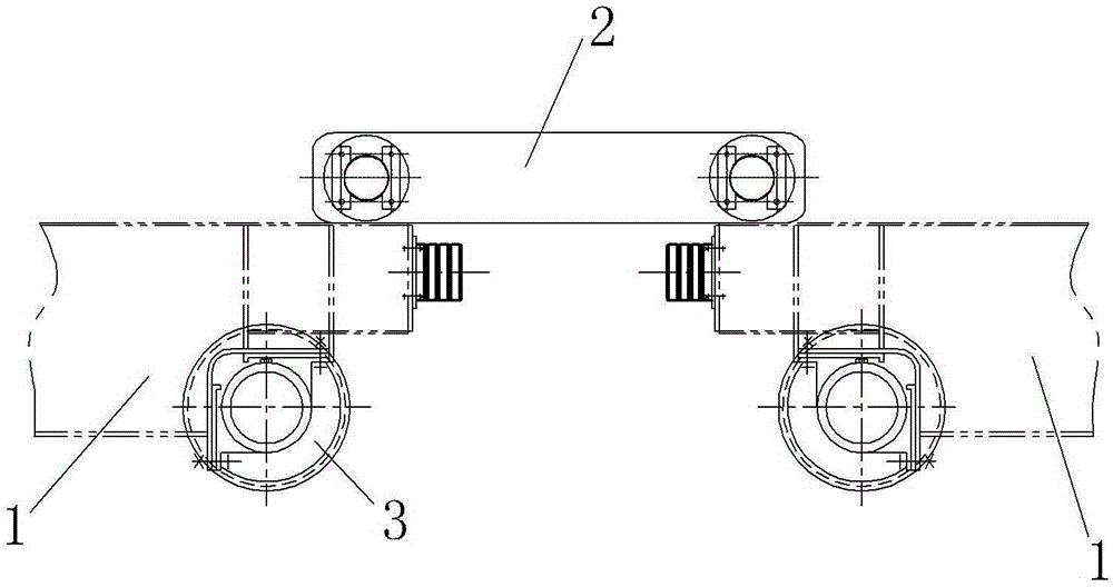
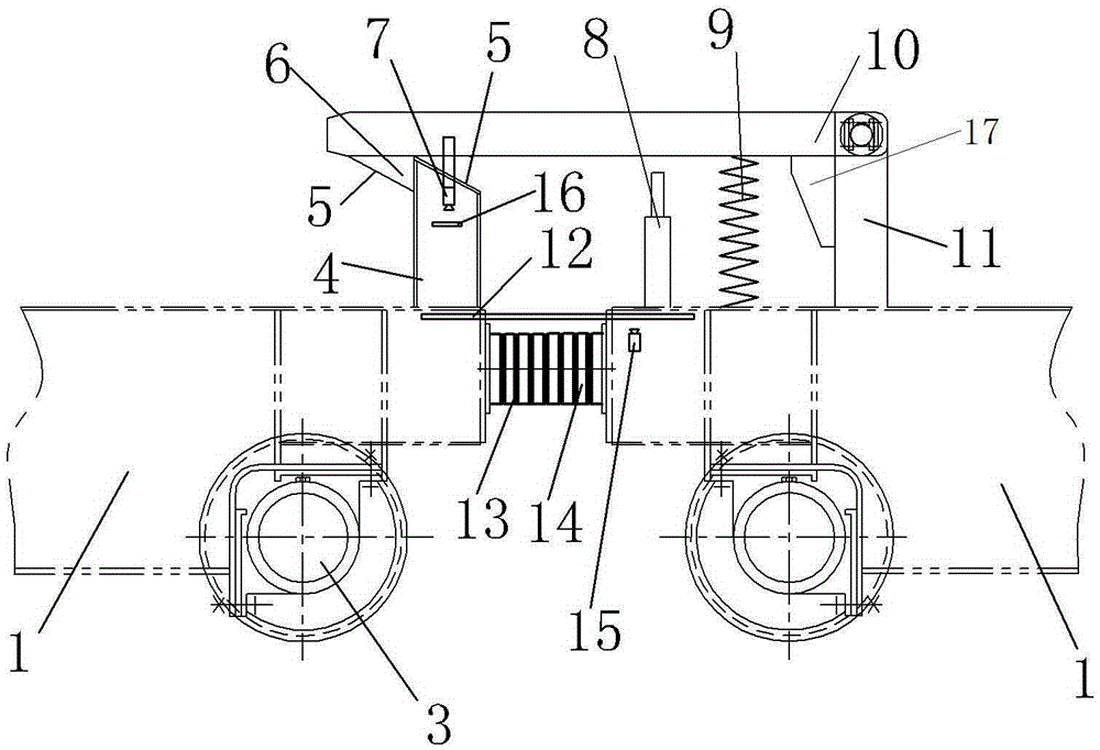
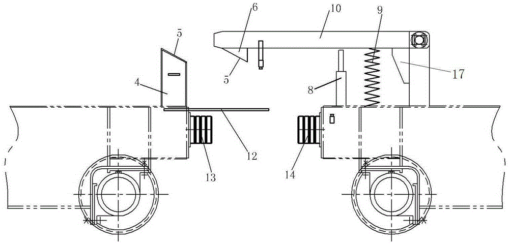
[0028] An implementation example of a crane assembly Figure 2~7 Shown: Including linkage connection device and two cranes arranged in the front and rear direction, each crane includes a main beam (not shown in the figure) extending in the left and right direction and end beams 1 arranged at both ends of the main beam, on the end beams A walking wheel 3 is provided, and the end beam in this embodiment is also called a walking beam. The linkage connecting device includes a bracket 11 and a block 4 respectively welded and arranged on the walking beams of two cranes. The bracket 11 is located on the front side of the block 4, and a swing rod 10 that can swing up and down is hinged on the bracket. It has a hook 6 which has a hook working position that is matched with the rear side of the stopper during the swinging process of the swing rod 10. A spring 9 is provided between the swing rod 10 and the walking beam at the front position. The upper end of the spring 9 is connected with...


PUM


Abstract

The invention relates to a crane assembly and a linked connecting device thereof. The linked connecting device comprises a bracket and a baffle block which are arranged on travelling beams of two adjacent cranes, respectively, wherein a swinging rod capable of swinging up and down is hinged on the bracket; a hook part is arranged on the rear end of the swinging rod and is provided with a hooking working positing matched with the rear side surface of the baffle block in a hooking way in a process of swinging up and down along with the swinging rod. When the two adjacent cranes need to be connected, the travelling beams of the two adjacent cranes oppositely move, and the swinging rod swings for making way for the baffle block; when the distance between the travelling beams of the adjacent two cranes enables the hook part to be at the rear side of the baffle block, the travelling beams stop movement, and the hook part can swing to the hooking working position with the swinging rod to match the rear side surface of the baffle block in a hooking manner, so that the front crane can drive the rear crane to link by virtue of hooking matching of the hook part and the baffle block, a bolt or a pin roll does not need to be installed when the crane linkage is realized, and the connecting efficiency of cranes is improved.

Description

Technical field [0001] The invention relates to a crane and its linkage connection device in the lifting field. Background technique [0002] In the manufacturing and transportation industry, some large workpieces or equipment often require two or more cranes to work together during lifting. This requires that when the cranes are traveling together, the distance between the hooks has a fixed requirement. The cranes can operate accurately and synchronously and the hook distance does not change during operation. The cranes need to be rigidly connected through the linkage connecting device. After the lifting is completed, the linkage connecting device is disconnected, and each crane can operate independently. [0003] The connection scheme between the crane and the crane in the prior art is such as figure 1 As shown: each crane includes an end beam 1 provided with traveling wheels 3, and the linkage connecting device includes a connecting beam 2 connected between the end beams of two ...

Claims


Application Information

Patent Timeline
Patent Type & Authority Patents(China)
IPC IPC(8): B66C13/00B66C9/00
Inventor 陈亮魏永顺祁鹏飞
Owner 北京云中未来科技有限公司
Why Eureka
Try Eureka