Indoor unit of air conditioner

A technology for indoor unit and indoor unit of an air conditioner, which is applied in directions such as airflow control elements, can solve problems affecting the overall appearance of the indoor unit, and achieve the effect of ensuring the appearance requirements

Active Publication Date: 2014-07-23
MIDEA GRP CO LTD
View PDF5 Cites 8 Cited by
  • Summary
  • Abstract
  • Description
  • Claims
  • Application Information

AI Technical Summary

Problems solved by technology

[0003] The object of the present invention is to provide an air conditioner indoor unit, which aims to solve the problem that the opening and closing door of the existing indoor unit has multiple seams when closing the air outlet, which affects the overall appearance of the indoor unit

Method used


Image

  • Indoor unit of air conditioner
  • Indoor unit of air conditioner
  • Indoor unit of air conditioner

Examples


Embodiment 1

[0038] The pushing mechanism 32 can be a telescopic rod (not shown in the figure), specifically the telescopic rod can be a cylinder, etc., the telescopic rod can be arranged inside the indoor unit housing 1, one end of which is fixed on the indoor unit housing 1, and the other end Then it is fixed on the opening and closing door 2, and it is perpendicular to the air outlet 11. Of course, when the rotating mechanism 31 is working, the telescopic rod will not affect the rotation of the opening and closing door 2 itself. When the indoor unit starts to work, the telescopic rod first stretches to push the opening and closing door 2 away from the outer surface 12 of the indoor unit casing 1. After the opening and closing door 2 is rotated, the telescopic rod starts to retract and pull the opening and closing door 2 to the indoor unit casing 1 Otherwise, after the indoor unit stops working, the telescopic rod first stretches and pushes out the opening and closing door 2, and then ret...

Embodiment 2

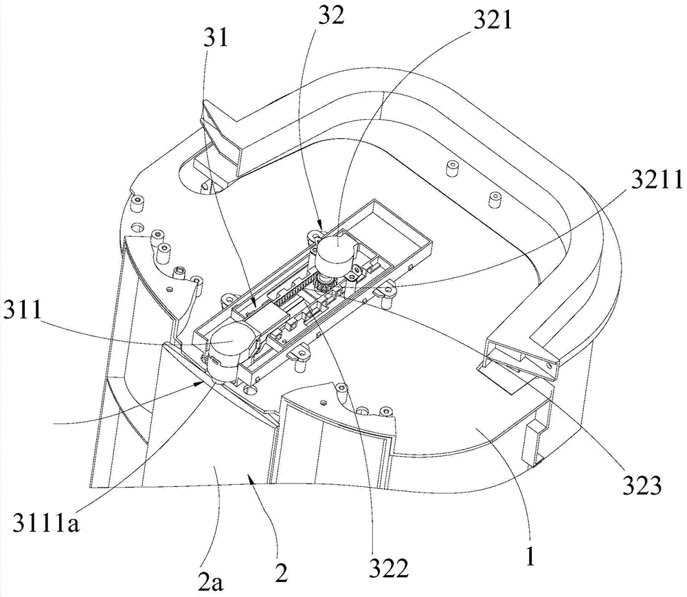
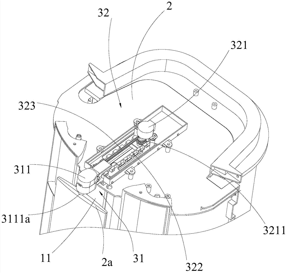
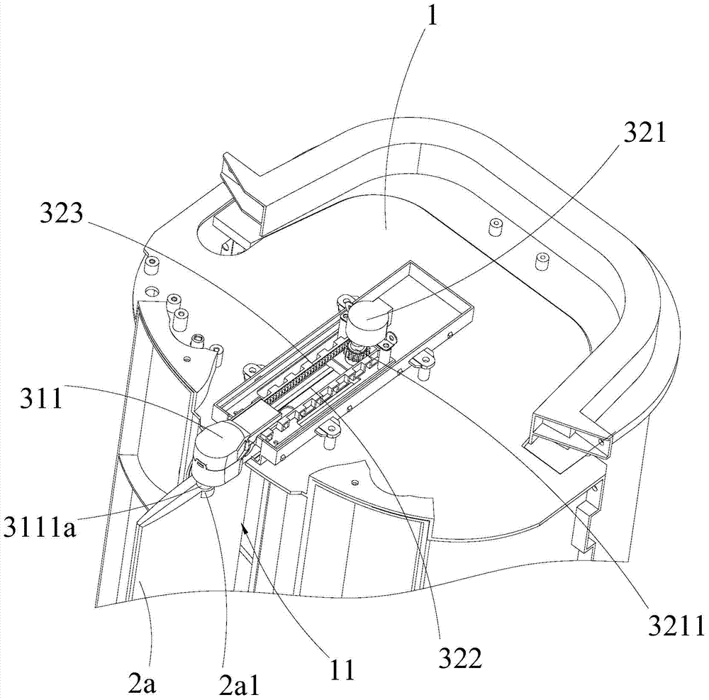
[0040] The pushing mechanism 32 includes a first driving member 321, a chute 322, and a rack 323. The first driving member 321 is fixed on the indoor unit housing 1, and is generally a driving motor. The chute 332 is perpendicular to the air outlet 11, and the rack 323 is laid along the inner wall of the chute 322, and it is slidably connected with the inner wall of the chute 332. The first drive member 321 has a rotatable first drive shaft 3211, and the first drive shaft 3211 is engaged with the rack 323. The first driving member 321 is fixed on the indoor unit housing 1, and after the first driving shaft 3211 rotates, the rack 323 slides along the inner wall of the chute 322; The chute 322 moves the second driving part 311 synchronously, and at the same time, the second driving part 311 can drive the opening and closing door 2 to move with the rack 323 along the direction perpendicular to the air outlet 11. The second driving part 311 also adopts a driving motor. The second ...


PUM


Abstract

The invention relates to an air conditioner, in particular to an indoor unit of the air conditioner. The indoor unit comprises an indoor unit shell with an air outlet, wherein the indoor unit shell is provided with a door used for opening and closing the air outlet. The indoor unit comprises a drive device, wherein the drive device can drive the air outlet to be in a closed state and can drive the door to be located in the indoor unit shell and make the area of the projection, in the direction vertical to the air outlet, of the door smaller than the area of the air outlet. According to the indoor unit, the door can be used for closing the air outlet to perform a dustproof function, meanwhile, when the indoor unit works, the door can be used for opening the air outlet and be contained in the indoor unit shell, and the requirement for the appearance of the indoor unit during operating can be effectively met; besides, due to the fact that the area of the projection, in the direction vertical to the air outlet, of the door is smaller than the area of the air outlet, after the air outlet is opened, and the door is of an integrated structure in design, and when the air outlet is closed through the door, no joint lines exist on the surface of the door and the requirement for the appearance of the indoor unit is met.

Description

technical field [0001] The invention relates to an air conditioner, in particular to an air conditioner indoor unit. Background technique [0002] As a household appliance, the air conditioner has been gradually applied to ordinary families. As an important part of the indoor unit of the air conditioner, the switch door mainly plays the role of opening and closing the air outlet of the indoor unit to prevent environmental dust from entering the housing of the indoor unit and affecting the normal operation of the indoor unit. In the traditional indoor unit, the air outlet of the indoor unit shell is a fence structure, and the switch door is also divided into multiple blade structures to cooperate with the air outlet, so that when the indoor unit stops working, the switch door closes the air outlet and the switch door closes the air outlet. There are many seams on the door, which greatly affects the overall appearance of the indoor unit. Although there is a switch door which ...

Claims


Application Information

Patent Timeline
Patent Type & Authority Applications(China)
IPC IPC(8): F24F13/10
Inventor 李向阳陈奎闫长林
Owner MIDEA GRP CO LTD
Why Eureka
Try Eureka