Automobile oil filler cap hinge module

A technology of fuel filler cap and hinge assembly, which is applied to vehicle parts, hinges with pins, door/window accessories, etc., can solve the problems of manual correction, low production efficiency, and difficulty in wearing sleeves at the same time, so as to achieve easy adjustment and consistency, improve Production efficiency, ensure the effect of appearance requirements

Inactive Publication Date: 2012-08-29
力帆科技(集团)股份有限公司
View PDF5 Cites 0 Cited by
  • Summary
  • Abstract
  • Description
  • Claims
  • Application Information

AI Technical Summary

Problems solved by technology

Since the fuel filler cap hinge 1 is a stamped part with many bends, springback deformation is likely to occur after stamping, and the welding positioning hole 12a on the fuel filler cap hinge 1 is not easy to align with the welding positioning hole on the fuel filler cap reinforcement plate 5. The two are not easy to fit on the positioning column of the welding fixture at the same time, requiring manual correction, which is time-consuming and laborious, and the production efficiency is low. Moreover, the positioning round holes on the coaxial line on the two welding parts are not conducive to adjusting the position of the fuel filler cap hinge 1 before welding. , making it difficult to adjust the gap difference between the fuel filler cap 6 and the side wall outer plate hole 7a (such as figure 2 shown)
Since the inner cover of the fuel filler is welded and fixed on the outer panel of the side wall, welding errors will inevitably occur. When the screw hole on the inner cover of the fuel filler is skewed, the hinge seat 2 connected with the screw will be skewed. Due to the welding error of other hinged stamping parts, the entire fuel filler cap assembly will be skewed in the hole 7a of the side wall outer plate, resulting in the surface difference between the fuel filler cap 6 and the side wall outer plate 7, and the two screws on the hinge seat 2 The mounting hole 2a is a round hole, and it is quite difficult to adjust the level difference by adjusting the mounting position of the hinge seat 2, which makes it difficult to ensure the smoothness of the fuel filler cap 6 and cannot meet the appearance requirements of the vehicle body.

Method used


Image

  • Automobile oil filler cap hinge module
  • Automobile oil filler cap hinge module
  • Automobile oil filler cap hinge module

Examples


Embodiment Construction

[0023] Below in conjunction with accompanying drawing and embodiment the present invention will be further described:

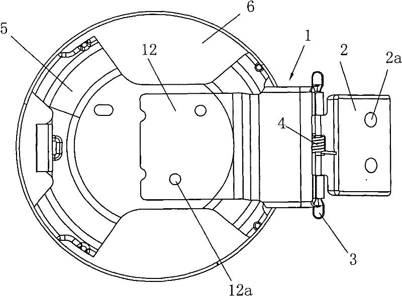
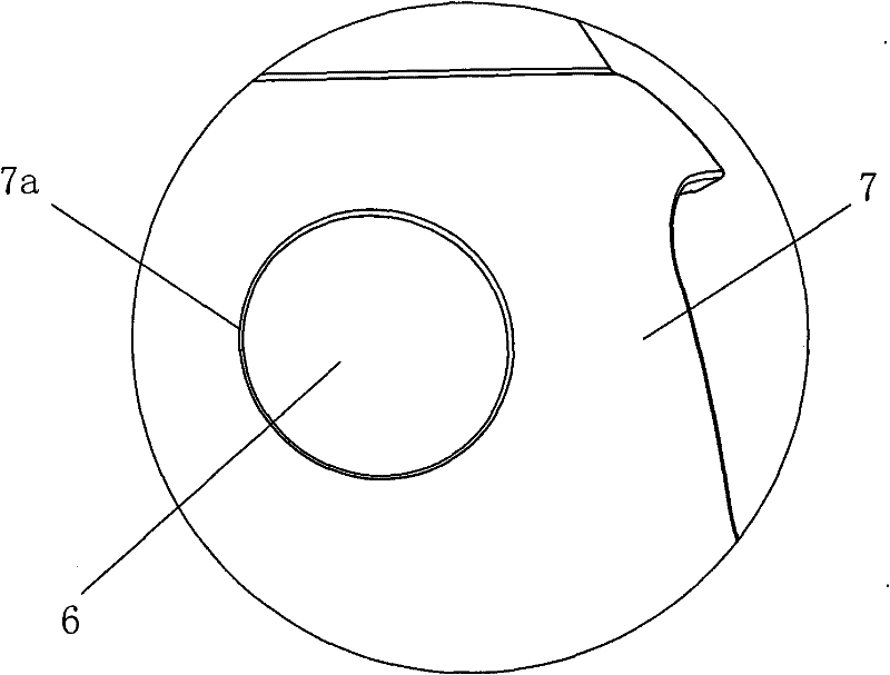
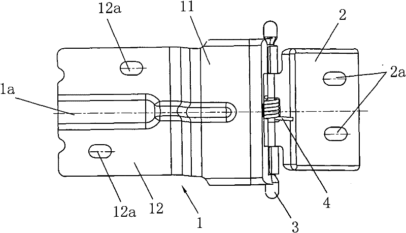
[0024] Such as image 3 with Image 6 As shown, the present invention is an automobile fuel filler cap hinge assembly, which is composed of a fuel filler cap hinge 1, a hinge seat 2, a rotating shaft 3 and a hinge spring 4, wherein the fuel filler cap hinge 1 and the hinge seat 2 are metal stamping parts, The fuel filler cap hinge 1 is hinged to the hinge seat 2 through the rotating shaft 3 .

[0025] Such as image 3 , Figure 5 with Image 6 As shown, the fuel filler cap hinge 1 includes a U-shaped bending part 11 and a horizontal mounting plate 12, one side of the opening end of the U-shaped bending part 11 is hinged with the hinge seat 2, and the other side is connected with the horizontal mounting plate 12. Both ends of the hinged end of the U-shaped bent portion 11 of the lid hinge 1 are curled outward to form two sections of hinge shaft holes 11a....


PUM


Abstract

The invention discloses an automobile oil filler cap hinge module which comprises an oil filler cap hinge (1), a hinge seat (2), a rotating shaft (3) and a hinge spring (4), wherein the oil filler cap hinge (1) is articulated with the hinge seat (2) by the rotating shaft (3) which is penetrated with the hinge spring (4); and a welding locating hole (12a) is welded on the oil filler cap hinge (1).The automobile oil filler cap hinge module is characterized in that mounting holes (2a) on the hinge seat (2) are strip-shaped; at least one of the welding locating holes (12a) on the oil filler cap hinge (1) is strip-shaped; and the axes in length direction of the strip-shaped holes are all parallel to the axis of the oil filler cap hinge (1). The automobile oil filler cap hinge module can conveniently adjust the matching clearance difference of an oil filler cap assembly and a side-wall shell plate hole, is convenient for adjusting the surface difference of an oil filler cap and a side-wallshell plate, improves production efficiency, and is easy to ensure the appearance of the automobile body at the oil filler.

Description

technical field [0001] The invention relates to an automobile fuel filler cap, in particular to a hinge structure for an automobile fuel filler cap. Background technique [0002] The automobile fuel filler cap assembly is installed on the side panel of the automobile body to meet the appearance of the automobile body and prevent fuel from splashing. The fuel filler cap assembly and the side wall outer panel must have a good matching relationship, such as the smoothness of the side wall outer panel profile, fit clearance and surface difference, etc., to ensure the appearance requirements of the car body at this place. Such as figure 1 As shown, the fuel filler cap assembly generally includes a fuel filler cap 6, a fuel filler cap reinforcement plate 5 and an automobile fuel filler cap hinge assembly, the fuel filler cap 6 and the fuel filler cap reinforcement plate 5 are welded together; The lid hinge assembly includes a fuel filler lid hinge 1, a hinge seat 2, a rotating s...

Claims


Application Information

Patent Timeline
Patent Type & Authority Patents(China)
IPC IPC(8): E05D3/02E05D5/02E05D5/06B62D25/24
Inventor 陈亚斌魏建芳
Owner 力帆科技(集团)股份有限公司
Why Eureka
Try Eureka