
Piston casting method and casting mold thereof

A technology for casting molds and casting models, which is applied in the directions of manufacturing tools, casting molding equipment, casting molds, etc., can solve the problems of increasing trachoma in castings, time-consuming and laborious, and reducing work efficiency, and achieves the improvement of as-cast hardness uniformity, and the method and steps are simple. , the effect of improving production efficiency

Inactive Publication Date: 2018-01-05
上海兆丰制冷配件有限公司
View PDF7 Cites 0 Cited by
  • Summary
  • Abstract
  • Description
  • Claims
  • Application Information

AI Technical Summary

Problems solved by technology

[0004] 1. Due to the large number of casting models in the single mold, the cooling rate in the middle and edge of the model is not uniform, and the as-cast hardness of the casting is easy to be uneven in the end.
[0005] 2. Since this solution requires sand cores, it is necessary to add a sand core making process, and the production of sand cores for each mold also reduces the work efficiency. At the same time, the use of sand cores will also increase the rate of defects such as sand holes in castings
[0006] 3. Since this scheme must adopt the deep gate feeding scheme, the surface of the finally produced blank pouring riser must be polished by a grinding wheel after separation, which is not only time-consuming and laborious, but also produces a large amount of dust that has a great impact on the environment
[0007] In addition, due to the large difference in the chemical composition of the product requirements, and since there are multiple castings in each mold, it is easy to cause product mixing if no special measures are taken.
Other manufacturers mainly use the method of engraving negative characters on the end face of the mold to distinguish them. After long-term use of this method, molding sand is easily entrained in the lettering groove, causing sand holes; Difficult management will affect the quality of later products

Method used


Image

  • Piston casting method and casting mold thereof
  • Piston casting method and casting mold thereof
  • Piston casting method and casting mold thereof

Examples


Embodiment Construction

[0033] In order to make the object, technical solution and advantages of the present invention clearer, the present invention will be further described in detail below in combination with specific examples and with reference to the accompanying drawings. It should be understood that these descriptions are exemplary only, and are not intended to limit the scope of the present invention. Also, in the following description, descriptions of well-known structures and techniques are omitted to avoid unnecessarily obscuring the concept of the present invention.

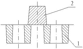
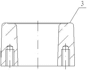
[0034] Such as Figure 2 to Figure 6 As shown, a piston casting method, which sets the casting model as a single-layer arrangement, a plurality of casting models are arranged in an orderly manner, the sprue is set at the center of the casting model, and the sprue and each casting model are passed through multiple The runners are connected; each casting model adopts the method of blank holder feeding to prevent the shrinkage...


PUM


Abstract

The invention discloses a piston casting method and a casting mold thereof. A plurality of casting patterns are distributed on a single layer and arrayed orderly; a running gate is arranged in the center of the casting patterns; the running gate and the casting patterns are connected through a plurality of pouring gates; each casting pattern is prevented from shrinkage depression by a blank pressing and shrinkage feeding method, and the blank pressing and shrinkage feeding method means that a riser is arranged between every two adjacent casting patterns for shrinkage feeding; the end faces ofthe casting patterns are provided with annular protrusions used for distinguishing the product specifications; and the upper surface of the risers are provided with strip-shaped protrusions used for distinguishing the product specifications. The piston casting method and the casting mold thereof have the beneficial effects that the production method is simple and high in production efficiency; thecooling speed of castings is even, the hardness uniformity of the castings is high, the protrusions are arranged on the casting patterns and the risers so that the product specifications can be easily distinguished, and management of foundry returns is convenient.

Description

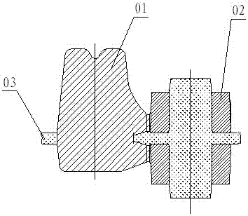
technical field [0001] The invention relates to the technical field of casting molds, in particular to a piston casting method with simple production method, high production efficiency, uniform casting cooling speed and high casting hardness uniformity, and a casting mold thereof. Background technique [0002] Casting mold means that in order to obtain the structural shape of the part, other easy-to-form materials are used to make the structural shape of the part in advance, and then the mold is placed in the sand mold, so a cavity with the same structural size as the part is formed in the sand mold. Then pour a fluid liquid into the cavity, and after the liquid cools and solidifies, it can form a part exactly the same as the shape and structure of the mold. [0003] At present, domestic casting pistons are all double-layer model methods, as shown in the attached figure 1 As shown, it includes riser 01, casting model 02, and core partition 03. The casting model adopts upper...

Claims


Application Information

Patent Timeline
IPC IPC(8): B22C9/20
Inventor 王云祥李昂
Owner 上海兆丰制冷配件有限公司
Learn More