
A transmission device for laser cutting

A laser cutting and conveying device technology, which is applied in auxiliary devices, laser welding equipment, welding/cutting auxiliary equipment, etc., can solve problems such as fault improvement, and achieve the effects of reducing faults, avoiding forehead damage, and reducing movement

Active Publication Date: 2016-05-11
OKE PLASTIC ZHANGJIAGANG
View PDF6 Cites 0 Cited by
  • Summary
  • Abstract
  • Description
  • Claims
  • Application Information

AI Technical Summary

Problems solved by technology

After the product to be cut is stopped during cutting, the laser cutting head moves in the two directions of X-axis and Y-axis according to the preset program, and cuts at the set position. Long-term use will cause the equipment to malfunction due to mechanical aspects. Greatly improve

Method used

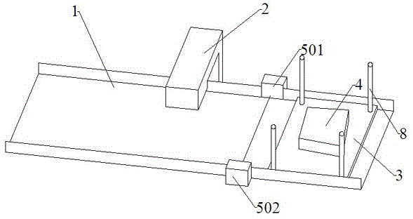
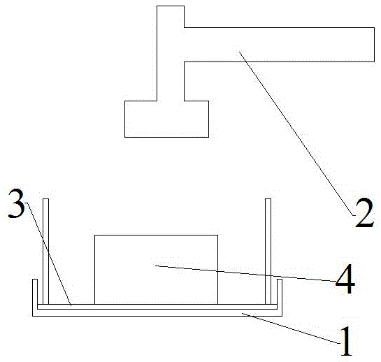
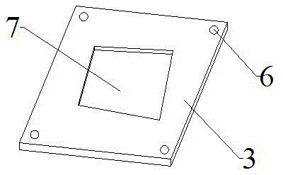

Image

  • A transmission device for laser cutting
  • A transmission device for laser cutting
  • A transmission device for laser cutting

Examples


Embodiment Construction

[0017] The present invention will be specifically introduced below in conjunction with the accompanying drawings and specific embodiments.

[0018] A conveying device for laser cutting, comprising an object to be cut 4, a conveying belt 1, a laser cutter 2 and a control device for controlling the laser cutter. The laser head of the laser cutter 2 can be manually adjusted in position.

[0019] A storage board 3 is also arranged on the conveyor belt 1 . In order to facilitate the quick placement of the storage board 3 on the conveyor belt 1 , baffles are provided on both sides of the conveyor belt 1 . The storage board 3 is set as a rectangle, and the width of the conveyor belt 1 is the same as that of the storage board 3, so that the storage board 3 can be directly and quickly placed on the conveyor belt 1 when in use, and there are baffles on both sides to prevent the storage board from being skewed up.

[0020] A groove 7 is arranged on the object board 3 , and the shape o...


PUM


Abstract

The invention discloses a conveying device for laser cutting. The device comprises a to-be-cut object, a conveying belt, a laser cutter and a control device, wherein the control device is used for controlling the laser cutter. The conveying device is characterized by also comprising an object placing plate, wherein the object placing plate is provided with a groove, the control device comprises a signal receiving device and a signal transmission device, and the width of the conveying belt is equal to the width of the object placing plate. The conveying device has the beneficial effects that the to-be-cut object can be fixedly arranged in the groove of the object placing plate; when the conveying belt moves the object placing plate to the position preventing the signal receiving device from receiving the signal, a laser cutting head can enter the cutting cycle, and start to cut after the to-be-cut object is moved to the position just under the laser cutting head, the mechanical movement of the laser cutting head is reduced, and the mechanical faults are greatly reduced; by arranging a support column, after cutting, the to-be-cut objects are stacked, so the damage caused by the mutual collision of the objects in the storage and transfer process is avoided.

Description

technical field [0001] The invention relates to a conveying device, in particular to a conveying device for laser cutting. Background technique [0002] With the mass production, the requirements for the production line are getting higher and higher. The current laser cutting method is to use the pause cutting method when punching holes, marking and cutting shapes. After the product to be cut is stopped during cutting, the laser cutting head moves through the two directions of X-axis and Y-axis according to the preset program, and cuts at the set position. Long-term use will cause the equipment to fail due to mechanical problems. Greatly improve. Contents of the invention [0003] In order to solve the deficiencies of the prior art, the purpose of the present invention is to provide a laser cutting transmission device that reduces the mechanical movement of the laser cutting head. [0004] In order to achieve the above object, the present invention adopts the following t...

Claims


Application Information

Patent Timeline
Patent Type & Authority Patents(China)
IPC IPC(8): B23K26/38B23K26/70
CPCB23K26/0838B23K26/38B23K37/04
Inventor 程忠贤
Owner OKE PLASTIC ZHANGJIAGANG
Learn More